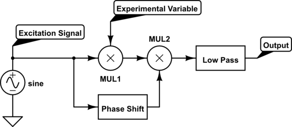
I have built several lock-in amplifiers: both analog and digital. The mathematical theory is identical for the digital and analog case. The technique is based on time-domain multiplication:

simulate this circuit – Schematic created using CircuitLab
- We produce an excitation voltage with a local oscillator. It is usually a sine wave, but could also be a square wave.
- We use that voltage to excite some experiment in which the amplitude of the voltage is effected by the thing I want to measure. Alternatively we can measure other signals not produced in this way, but at that point a phase sensitive detector is probably not desired.
- We then demodulate the signal with a multiplier MUL2. We can optionally shift the phase of the reference signal to produce a quadrature indication. It is common to do both at the same time.
- The product is low pass filtered in order to remove the content at frequencies other than the frequency of interest (noise, the excitation frequency, the experimental signal at other phases, ...)
I find it easiest to think of in the frequency domain as convolution. See a quick explanation in this video.
One can implement the above theoretical concept either with analog components, or by using converters (a DAC after the excitation signal is generated and an ADC to read the output of the experiment) and then digitally computing the phase shifted reference, product, and low pass filter (perhaps a moving average). The math doesn't care about the digitization, provided that the samlping rate is adequately fast.

