0
\$\begingroup\$

In analog communication, DSBSC (double side band suppressed carrier) is way of modulating signal.

In this the carrier is simply multiplied with the message signal.

At the demodulator, the carrier is multiplied back which gives the message signal back.

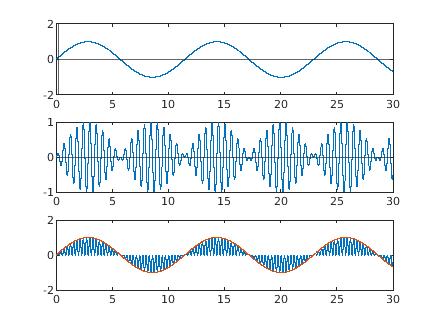
enter image description here

  • The first signal is my message signal
  • The second is the modulated signal
  • The third is the demodulated signal i.e I can get the msg by simply tracking the peak voltages

Now the demodulation process seems to be complete but the part that I am missing is a low pass filtee at demodulator. Why is it required? I have my signal back. Why should I pass it through a low pass filter? All the books have the filter.

Please explain why the low pass filter is required after the demodulator.

Matlab code


t=0:1e-4:30;
f=5;
y=sind(2*pi*f*t);
subplot(3,1,1)
plot(t,y)
hold on
yline(0)
xline(0.2)
ylim([-2 2])
hold off
subplot(3,1,2)
y1=sind(2*pi*100*t);

y3=y1.*y;

plot(t,y3)
hold on

yline(0)
hold off
subplot(3,1,3)

y4=y3.*sind(2*pi*100*t);

plot(t,y4)
hold on
ylim([-2 2])
plot(t,y);
hold off

\$\endgroup\$
16
  • \$\begingroup\$ which LPF where? \$\endgroup\$ Commented Oct 15, 2020 at 14:51
  • \$\begingroup\$ You tell me, whether the first graph is the same as the third graph. \$\endgroup\$ Commented Oct 15, 2020 at 14:51
  • \$\begingroup\$ LPF at demodulator \$\endgroup\$ Commented Oct 15, 2020 at 14:51
  • \$\begingroup\$ @user253751 no it just seams to be scaled to 2 . \$\endgroup\$ Commented Oct 15, 2020 at 14:52
  • \$\begingroup\$ It looks like it has some high frequency content in it too @NewtonNadar \$\endgroup\$
    – Colin
    Commented Oct 15, 2020 at 14:53

2 Answers 2

1
\$\begingroup\$

The Third is the demodulated signal i.e I can get the msg by simply tracking the peak voltages

A simple peak detector will rise to the top-most peak and stay there (the maximum voltage peak of the original message will be captured). So you must modify the simple peak detector so that it decays toward zero as time passes, else the original message bottom-most voltage won't be captured....this is starting to look like a low-pass filter. Another problem with peak detectors is their poor performance where the demodulated message includes noise.

Yes, the original message can be reconstructed by sampling the demodulated signal at the moment of each +ve peak. This method requires knowledge of carrier phase, and requires a phase-locked-loop to track 2xcarrier frequency.
OP has used this method, since the demodulator magically has used a re-constructed carrier frequency that is phase-locked to the modulator carrier frequency:

y4=y3.*sind(2*pi*100*t);

This phase-locking method has problems: for example, if the message is at zero, there's no carrier for the phase-locked-loop to track. In stereo FM, this problem is avoided by always transmitting a little bit of 19 kHz subcarrier (by adding a DC offset to the modulator's message signal). But this is no longer pure DSB-SC. And you still have the problem of poor noise performance, if you don't add a low-pass filter.

\$\endgroup\$
1
\$\begingroup\$

The third graph contains the demodulated signal (blue line). It clearly has two frequencies in it: a low frequency (of the original message signal) and a high frequency.

One method to get the low frequency message signal out of the combined singal is to use a low pass filter.

A peak detector would not work with suppressed carrier signal since you need a valley detector for the negative half cycles! (Look carefully at the demodulated signal (blue line) from 6 s to 12 s time duration. The message signal is hidden in the valleys not the peaks!)

\$\endgroup\$

Your Answer

By clicking “Post Your Answer”, you agree to our terms of service and acknowledge you have read our privacy policy.

Not the answer you're looking for? Browse other questions tagged or ask your own question.