I'm trying to build a circuit which allows an Arduino to control 6 channels of lighting from an old Strand Act 6 Dimmer.
These dimmers have 8-pin DIN connector on them like this specification. Pin 7 is +10V, Pin 8 is GND, and Pins 1-6 control the dimmers on channels 1-6. This is so that a variable resistor can be connected from GND to +10V, with its output going to one of the channels (so no powered controller is needed). However, I'd like to control 6 "variable resistors" from my Arduino using PWM.
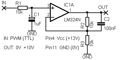
I'm following this guide. My Arduino outputs PWM on 6 pins, each of which goes through its own filter circuit:
which produces a voltage between 0 and 10v at OUT. My question is: this 0-10V is relative to the Arduino's GND and +12V input power. Will simply connecting the OUT of each filter circuit and GND to the corresponding pin on the DIN connector work, or do I have to somehow make the 0-10V OUT correspond to the +10V/GND coming from the dimmer?

