2
\$\begingroup\$

I am quite new to this and am struggling to read through the data sheets of the Sparkfun 16 segment display, datasheet here. I have managed to get all of the LEDs wired up through a LED driver, with 7v input and all pulling through a single resistor of 220 ohm.

As the short segments are one LED and the long ones are two, as soon as I switch on any of the short segments all the other ones are short circuited and switch off. Despite my best efforts I am unable to come up with a good solution to this, can anyone help?

--- Extra Information ---

LED Driver is the TLC5916IN datasheet here

The drivers are set up in a breadboard inside the pins of the LED display, so at the moment they are directly connected through the breadboard. If they need to be moved to accomodate extra resistors then that can be done, would just rather not if possible.

\$\endgroup\$
1
  • \$\begingroup\$ Which LED driver are you using and how do you have the display wired? \$\endgroup\$
    – EM Fields
    Commented May 17, 2015 at 16:22

2 Answers 2

1
\$\begingroup\$

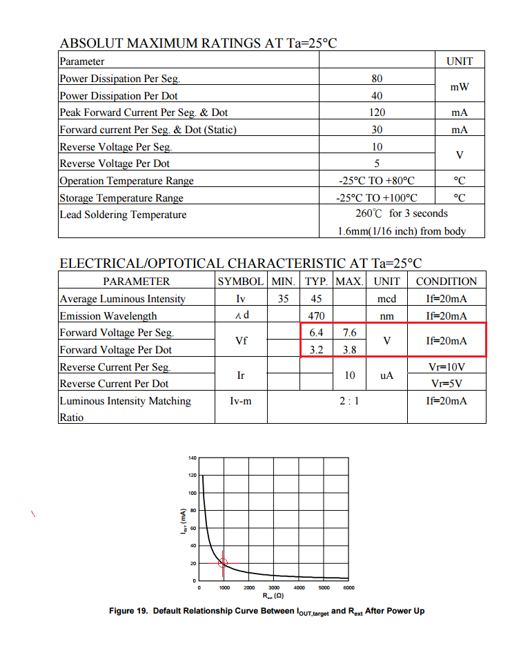
Excerpts from the display and driver data sheets, below, indicate that Vf for a 2 LED segment with 20mA through it can be as high as 7.6 volts, and for a 1 LED segment (a "dot"), with the same current running through it, 3.8 volts.

That means that your LED supply should be in the vicinity of 8 volts in order to have enough headroom to compensate for the drivers' Vce(sat), and should be able to source at least 320mA (16 segments X 0.02A) in order to light up all the segments at once without dimming.

The curve for Rset shows that for currents of 20mA into each of the driver's output sinks, Rset should be in the vicinity of 1000 ohms.

In order to make your widget work properly, then, you'll need to increase the LED supply voltage as well as Rset.

Note, however, that the LED supply voltage will exceed the driver's Vcc spec, so you'll need to make sure that Vcc is within its specified limits.

enter image description here

\$\endgroup\$
3
\$\begingroup\$

With a simple LED driver that does not control the LED currents, you require a separate current-limiting resistor for each segment, with a higher value for the one-LED segments than for the two-LED segments, to get consistent brightness between segments.

If the LED driver you are using limits the LED current, you may not need any resistors.

\$\endgroup\$
4
  • \$\begingroup\$ The drivers I am using are the TLC5916IN, which are "current controlled", which I presume is what you mean. (it has an external resistor to set the current) So do I have the wrong resistor set up? \$\endgroup\$
    – longstaff
    Commented May 17, 2015 at 16:44
  • \$\begingroup\$ The TLC5916IN is a constant current LED driver, so you don't need any resistors, including the single 220 ohm resistor on the common anode. The LED current will be set by the resistor on the RSet pin of the driver. \$\endgroup\$ Commented May 17, 2015 at 16:54
  • \$\begingroup\$ Perhaps I was not clear enough, the 220 ohm resistor is on the RSet pin, does this problem mean that the resistor is too low? \$\endgroup\$
    – longstaff
    Commented May 17, 2015 at 17:29
  • \$\begingroup\$ @longstaff: In a word, yes. \$\endgroup\$
    – EM Fields
    Commented May 17, 2015 at 18:03

Your Answer

By clicking “Post Your Answer”, you agree to our terms of service and acknowledge you have read our privacy policy.

Not the answer you're looking for? Browse other questions tagged or ask your own question.