0
\$\begingroup\$

I was working with a 7-Segment display and saw that there is no 'ground', only COM 1 and COM 2 which I do not understand their meanings, either.

Currently, I have the positive rail connected to COM 1 and it seems to be working fine. It seems to work also when I have the positive rail connected to COM 2.

I am using the display to display binary digits, with each digit being a segment of the display. I am using a 4-Bit Binary Counter 74HC93 to make the binary digits, from descending order (15...0).

The weird part is that the wires from the Binary Counter go to the display, but never go to ground from what I see, which breaks the laws of electricity and physics. The display lights up.

Now I use a XOR Gate 74HC86 (because circuits.io does not have a working NOT gate, so I keep value A at 1 constantly, and then use it as a NOT gate), and when I hook up the output of A and B, it does NOT light up one of the segments of the 7-Segment display (I tried all of them), but DOES light up a standard LED. It seems to follow the laws of electricity and physics.

Please explain how I can use the XOR gate to light up one of the segments of the display, what COM 1 and COM 2 means, and how lighting up one of the segments WORKS from the 4-Bit Binary Counter 74HC93.


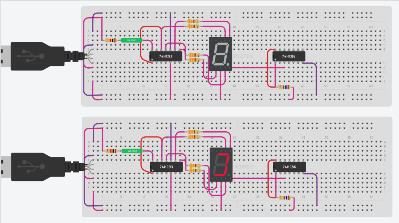
Here's a diagram on a breadboard with power on and off (Made on circuits.io):

first

Notice how the DP pin is connected, although isn't lighting up.


To verify that it isn't the XOR gate:

third

(If you couldn't tell, the LED is lit)

Lastly, it seems to "work" if you have some of the output going to ground. I set up an LED WITH the display, and it fried both; very strange.

If I can have any explination, how to make it work, what COM 1 and COM 2 is, that would be greatly appreciated. Thanks!

\$\endgroup\$
5
  • \$\begingroup\$ What does the datasheet say? It will give you a internal schematic of the 7-seg display. Also, not all 7-seg displays are configured the same inside \$\endgroup\$
    – tangrs
    Commented Jan 9, 2017 at 2:30
  • \$\begingroup\$ Circuits.io currently shows no datasheet, so I will try and find the most related one. \$\endgroup\$
    – Blake
    Commented Jan 9, 2017 at 2:31
  • 2
    \$\begingroup\$ Come on!! Get with it and use a proper schematic. I am out of here not willing to spend 1 millisecond looking at these stupid protoboard fakeups. \$\endgroup\$ Commented Jan 9, 2017 at 3:50
  • 1
    \$\begingroup\$ Michael; Even if I don't have a schematic, you should atleast try and spend a 'millisecond' trying to understand what happened, with your 28,000+ reputation you have most likely seen something of the sort before. I understand where you are coming from, although. \$\endgroup\$
    – Blake
    Commented Jan 9, 2017 at 23:47
  • \$\begingroup\$ Now that I can properly understand the sites, just look up "7 Segment Display" and the first result, (electronics-tutorials.ws/blog/7-segment-display-tutorial.html), shows you an idea of the Common Anode and how all other pins other can COM 2 are cathodes. Now, yes, if I were using a non-general component, I would KNOW the datasheet and know the schematic, but since the program I am using has a "general" seven-segment display, I just wanted to know some basic logic behind it. \$\endgroup\$
    – Blake
    Commented Jan 9, 2017 at 23:52

1 Answer 1

1
\$\begingroup\$

Self-Answered

With some playing around, I realized COM 1 is the Common Anode. COM 2 I still do not know the meaning of. A-G and DP pins are CATHODE meaning that they should be connected to ground, and are POWERED by the Common Anode.

\$\endgroup\$
5
  • 1
    \$\begingroup\$ Probably COM2 is the anode for the decimal point. Connect DP through a limiting resistor to ground and see what happens. \$\endgroup\$ Commented Jan 9, 2017 at 3:02
  • 2
    \$\begingroup\$ COM1 and COM2 may both be for the common anodes. Some segments may be connected to COM1, and some to COM2, or, more likely, COM1 and COM2 may be connected together internally. \$\endgroup\$ Commented Jan 9, 2017 at 3:31
  • \$\begingroup\$ The segment cathodes will be grounded through the IC driving the segments. \$\endgroup\$ Commented Jan 9, 2017 at 3:37
  • \$\begingroup\$ displays may have two common anodes, some devices (eg: LM8560 - found in LED digital clocks ) relay on having separate anodes for the top and bottom half of the display. \$\endgroup\$ Commented Jan 9, 2017 at 6:01
  • \$\begingroup\$ Good ideas, but all the segments seem to work fine without having COM2 even connected to anything, even DP. Possibly a transistor that relies on COM1, and then COM2 amplifies it, but that was just a thought. \$\endgroup\$
    – Blake
    Commented Jan 9, 2017 at 23:57

Your Answer

By clicking “Post Your Answer”, you agree to our terms of service and acknowledge you have read our privacy policy.

Not the answer you're looking for? Browse other questions tagged or ask your own question.