0
\$\begingroup\$

I'm making this circuit: circuit
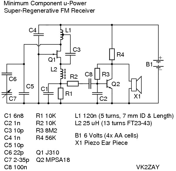
(source: vk2zay.net)

where X1 is a piezoelectric speaker or ear piece. However, the only kinds of speakers I can get in time to finish this project are electromagnetic ones (we found one in a Father's Day card, and another from a radioshack project).

The page here that explains the circuit makes it seem like the piezoelectric speaker is required, but is there a way that I can modify this circuit to use an electromagnetic speaker instead of a piezoelectric one?

\$\endgroup\$
5
  • \$\begingroup\$ I have no idea what tag this fits under, so please feel free to correct me if I'm wrong \$\endgroup\$ Commented May 19, 2015 at 23:35
  • \$\begingroup\$ You can always find piezo speakers inside electronic watches. As long as they can make a "beep" sound. \$\endgroup\$
    – Zulu
    Commented May 21, 2015 at 6:41
  • \$\begingroup\$ Is that a speaker? Or is that just a buzzer? \$\endgroup\$ Commented May 21, 2015 at 12:51
  • \$\begingroup\$ It's a piece of ceramic sandwiched between two sheets of metal. If you want it to buzz, you can make it buzz. If you want it to speak, you can make it speak. Like pretty much any piezo speaker, it won't be a high-fidelity sound (it has a few sharp resonances in the audio range), but you'll be able to understand it. \$\endgroup\$
    – Zulu
    Commented May 21, 2015 at 23:37
  • \$\begingroup\$ +Zulu True, but when I started sorting through my parts bins for those things (crystal radio stuff) I quickly realized they all have different frequency responses, volumes, etc. \$\endgroup\$ Commented Jul 13 at 23:32

1 Answer 1

1
\$\begingroup\$

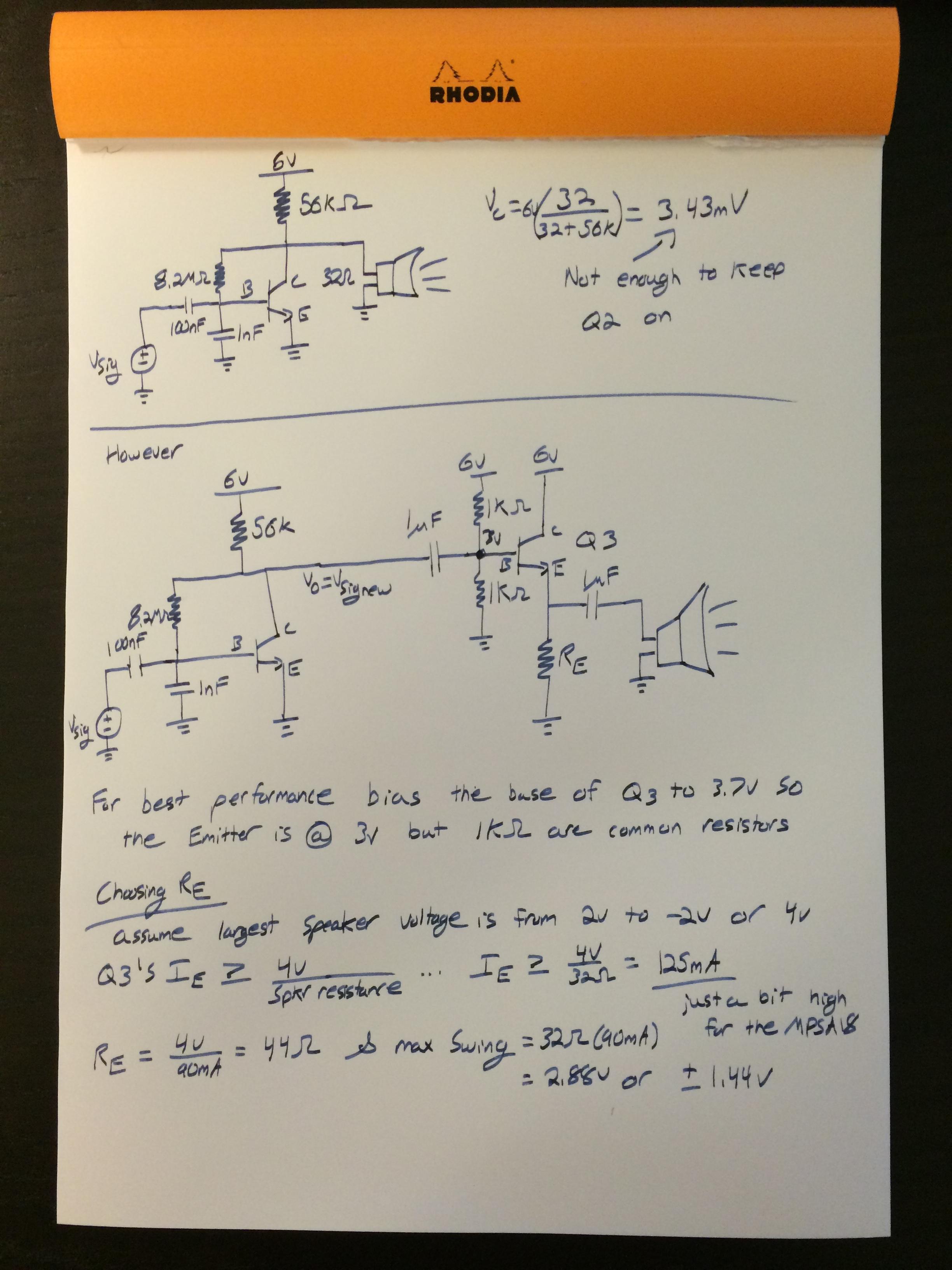
By simply attaching a low resistance EM speaker you will not be able to keep Q2 working, see the top part of my solution posted in the image. However it is possible to accomplish with another transistor. Create a two stage amplifier where the output stage is an emitter follower. This will buffer the volume amplifier created with Q2, allowing you to drive the low resistance speaker. You will not have great battery life and your volume will tend to be less than what the piezoelectric speaker produced but it will certainly work. If you find you need more gain increase the 1K ohm resistors used to bias the base of Q3. Make sure the base equivalent resistance allows for enough dc current to keep Q3 on.

PS: This solution assumes you have a greater than or equal to 32 ohm speaker.

Let me know if you need more explanation or help.

-Ryan

enter image description here

\$\endgroup\$
5
  • \$\begingroup\$ Thanks for the answer. I don't have a single 32 ohm speaker, but I do have two 16 ohm ones, which I assume I can just put in series.. \$\endgroup\$ Commented May 20, 2015 at 0:40
  • \$\begingroup\$ That would work, each speaker produces half the volume. \$\endgroup\$
    – Rwsselby
    Commented May 20, 2015 at 0:43
  • \$\begingroup\$ I also noticed I made a mistake calculating Re it should have been 2.3V/90mA = 25 Ohm \$\endgroup\$
    – Rwsselby
    Commented May 20, 2015 at 0:44
  • \$\begingroup\$ For Q3, what kind of transistor should it be? \$\endgroup\$ Commented May 20, 2015 at 0:45
  • \$\begingroup\$ You can use the same as Q2... the MPSA18. You can also use a general purpose transistor such as the 2N3904. Anything with a DC current rating of >=100mA. If you use a transistor that is good for 500mA then by all means decrease the emitter resistor so you can power a lower resistance speaker. \$\endgroup\$
    – Rwsselby
    Commented May 20, 2015 at 0:47

Your Answer

By clicking “Post Your Answer”, you agree to our terms of service and acknowledge you have read our privacy policy.

Not the answer you're looking for? Browse other questions tagged or ask your own question.