Switching regulators and switching controllers are very similar, and essentially perform the same function. Both of them are DC to DC converters.
Both switching regulators and switching controllers can be obtained/configured in either buck (output voltage < input voltage), boost (output voltage > input voltage), or both topologies.
The buck/boost mode is useful for battery operated circuits, for example you might have a 3.3v circuit, powered from a 3.6v battery which is initially charged up to 4.2v. The battery voltage drops to 3.3v while in buck mode, and then falls further below 3.3v where it uses boost mode.

The circuits uses a combination of one or more FETs represented by the little switches in the diagrams above) and an inductor to carry out their work.
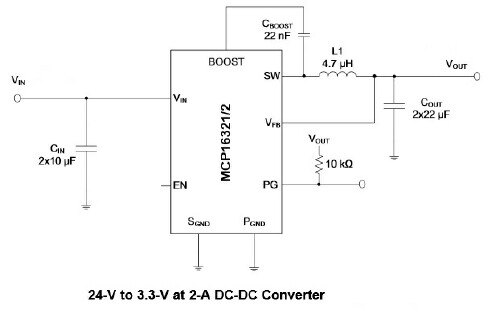
Switching regulator ICs contain all of the necessary hardware, except for the inductor and a few resistors and capacitors, inside the one chip. In particular, the switch mode FET is inside the regulator. As a result, these chips can't handle too much current, usually only an amp or two, otherwise they would get too hot. Here is a typical circuit for a 24v to 3.3v 2A buck type switching regulator:

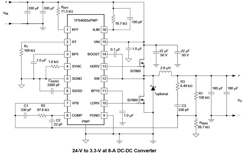
With switching controllers, the switching function is done external to the chip. This allows for much higher currents than switching regulators, since the controllers themselves don't have to handle the current -- just the external FETs which can be sized as necessary for the task. Here is a typical circuit for a 24v to 3.3v 8A buck type switching controller:
$$ $$

Switching controllers also offer a lot more configurable options, which is why this circuit is considerably more complicated than the previous one.


