69
\$\begingroup\$

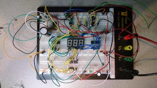
I recently finished building a circuit showcased in a beginner’s electronics book. I have included the picture of my creation below because I think it may become relevant to the question.

Picture of circuit on breadboard with many wires

At the beginning of the build process, the instructions specified to add a "smoothing" 100 microfarad capacitor to be placed right by where the power supply cables were connected to the board. I decided not to bother with that step because I was using a quality power supply so I didn’t think I needed that "smoothing" capacitor (big mistake).

It wasn’t long before I started experiencing weird and inexplicable odd circuit behavior and after a lot of troubleshooting and getting nowhere, it occurred to me to add the smoothing capacitor to the circuit. As soon as I added the capacitor to the circuit the problems went away, but I found myself wondering how is possible that such a capacitor mattered so much given that my circuits uses a measly 50 milliamps of total power and I have what I think is a reasonably good power supply (Rigol DP832).

To make matters more interesting, I decided to move the smoothing capacitor away from the center of the board off to one end of the board and to my surprise the problems began again. Why such a big difference just by placing the capacitor in a different place on the board?

I decided to add a beefier 8200 microfarad capacitor (that is 82 times bigger than the previous one) thinking that this would put an end to all my problems but to my surprise once again, that still did not fix the problem. I actually had to move the capacitor back to the center of the board to make things go back to normal.

That wasn't the only issue, even with the capacitor in "perfect placement", I tried to power a small mechanical relay by using the same power from the circuit and every time the relay triggered my circuit would “reboot”.

So the question is, are all circuits that sensitive to even the smallest change in electric fluctuation? Or is the problem due to my cheesy circuit prototyping skills and an inefficient breadboard?

The IC used in the circuit are:

  • NE555P (Precision Timers).
  • CD4026BE (CMOS Decade Counters/Dividers).
\$\endgroup\$
5
  • 18
    \$\begingroup\$ I would like to say that you pose a very good question well put. Such things as the picture consideration right up front and a lot of information. I'm very happy at the end of a long day to see a question like this to offset a few of the one sentence "google first hit" questions. Thank you for that. Keep it up. \$\endgroup\$
    – Asmyldof
    Commented Jun 25, 2015 at 1:42
  • 3
    \$\begingroup\$ Excellent question. Good to see what you tried and your reasoning - what made sense, what didn't and what you did as a consequence. A superb learning experience and an excellent approach. | Asmyldof's D3 is standard practice and essential. His D1 & D2 are often not used but can help greatly. Note his C1 which helps keep current demand surges inside its own area. Use small caps (often 0.1 uF AT ICs from Vcc to ground to provide local reservoirs for high frequency switching pulses that otherwise can affect other ICS, AND which also act as a "pool" for incoming noise ripples 'to fall into'. \$\endgroup\$
    – Russell McMahon
    Commented Jun 25, 2015 at 1:49
  • \$\begingroup\$ Congratulations on having your first experience with decoupling issues on a breadboard, where you could easily experiment. Many of us were not nearly so lucky. ;) \$\endgroup\$ Commented Jun 25, 2015 at 6:23
  • 1
    \$\begingroup\$ Man, you just proved that worst luck makes best learning experience ever. \$\endgroup\$
    – Nicolas D
    Commented Jun 25, 2015 at 15:00
  • 1
    \$\begingroup\$ This was an attempt to create a canonical question so that all other past, present, and future questions about spaghetti antennae can be closed as duplicates, right? \$\endgroup\$
    – Ben Voigt
    Commented Jun 25, 2015 at 18:15

7 Answers 7

58
\$\begingroup\$

The advised capacitor is a long-lead buffer, so to speak.

Even if you had a perfect power supply, the cables that run to your design are far from perfect. And that's not your fault, it's just how cables are. I believe some rapper wrote a song about that... I'm pretty sure it was about cables anyway.

Your cables firstly pick up noise. Secondly they have silly characteristics that you will learn about later at some point in more detail, but basically for high frequency signals (such as digital circuitry makes) they have a very high reluctance to conduct current, possibly even only 50 mA. Those signals are hard to transport over just any cable. You can see it for now as the cables being a bit slow to react. If you switch on a current they will take some time to supply that steadily, so if you switch it often, you'll start to notice a lot of noise on the power supply.

Adding that capacitor will allow your high frequency switching currents to be taken from the capacitor, so the cables can supply just the short-term average, and normal DC leads are very good at short term average near-DC, they can do many amps at that and so can your supply: Everyone happy.

In fact, many design guides for voltage management or voltage regulator chips specify an input capacitor of 2.2 μF, for example, parallel to a dotted 22 μF or larger, with an asterisk saying "if the incoming power cables are longer than X or Y, regardless of power supply used, add the 22 μF (or more) capacitor for stability and better noise rejection".

It may even be better to keep the 100 μF capacitor, because the 8200 μF capacitor will have a larger internal resistance, unless it's also much, much larger physically. The internal resistance of a capacitor determines how good it is at taking away the ripple of low-current high frequency signals. Smaller is better in most cases with first input capacitors like this one. But, with voltage regulators, that doesn't always apply for all input/output capacitors, so once you get to those beware! But that's not for now.

You can be happy about not everything being this sensitive, slowly switching or high frequency digital alike, there are many robust things that are much less sensitive to reboots, but it is often still a very good idea to add some capacitance if a board or design is powered with wires or sometimes even through a connector between boards. It doesn't always have to be as large as 100 μF, but a little to take the edge off (pun for the more weathered reader intended). Having no noise to work with is always better than having to work with noise.

The reason the capacitor between the power wires and the circuit works better than the circuit between the power wires and the capacitor is because the trace inductance (whether it's a PCB or bread board) will limit the response of the capacitor, if you then have power wires nearby, your circuit will ask them to supply some of the current as well, which will cause the same kinds of dips, but possible in a lower order. You are already basically putting your switching noise onto the cables and the cables already react to it. When your noise sees the capacitor first, even with some inductance in the traces, the noise will not go into the cables and not cause any further problems, which reduces the noise your circuit sees by a much greater factor.

Edit: Note: The above about capacitor position is severely simplified in some respects, but it generally conveys the idea well enough. To clarify it should suffice, but there are many dynamics to things like this. In later years looking back, you may find this to be a bit lacking. But you don't need to know all that right now. This will do.

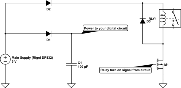
The reason with a relay and a capacitor and shared power things go wrong, still, is because the current spike of your relay is too large for the capacitor to help with and then the cables can't keep up either, or because the relay release creates a voltage spike. A solution could be, if your design can handle a diode-drop:
schematic

simulate this circuit – Schematic created using CircuitLab

D1 prevents anything powered by the DR832 from stealing power from your digital buffering capacitor C1. D2 prevents the relay from making any significant noise on your supply and D3 catches any power spikes the relay still makes when you turn it off.
\$\endgroup\$
5
  • 1
    \$\begingroup\$ Excellent suggestions. \$\endgroup\$
    – Russell McMahon
    Commented Jun 25, 2015 at 1:50
  • \$\begingroup\$ @RussellMcMahon Thanks. Always nice to get a kudos from a many-k-rep member ;-) \$\endgroup\$
    – Asmyldof
    Commented Jun 25, 2015 at 17:14
  • \$\begingroup\$ You can type μ in SE by using the HTML entity, μ. \$\endgroup\$
    – KRyan
    Commented Jun 26, 2015 at 14:28
  • 2
    \$\begingroup\$ I thought the problem with too large caps was their inductance, not their resistance? Can you clarify this? \$\endgroup\$
    – avl_sweden
    Commented Jun 26, 2015 at 17:07
  • \$\begingroup\$ @avl_sweden higher inductance is probable, much more probable is a higher resistance. Bidirectional rolling of plates in electrolytics isn't very expensive any more, yielding comparatively low inductance, but length will always be a thing until they start tapping the foils at multiple places for the leads. Which is quite hard to do right. But you are right that it's a chance and it won't help. \$\endgroup\$
    – Asmyldof
    Commented Jun 27, 2015 at 7:15
15
\$\begingroup\$

The combination of solderless breadboards and long wires is deadly, especially when you get to any complexity. Try this as an experiment: replace all your ground and power wires with jumpers which are as short as possible. Ideally, they should be so short that there is no slack in them at all. Also, put a capacitor from power to ground at each IC and display. Use 0.1 uF ceramics for digital power, and 1-10 uF tantalum electrolytics for the analog power. In all cases, make the connections as close to the power pins as you can. It's best if you don't even use extra jumpers - just plug the cap leads in next to the IC pins.

Finally, I notice you have 3 breadboards ganged together. In addition to the power and ground connections at the top of each breadboard, run short jumpers just below your ICs connecting the grounds and power busses together, so that the connections form a rectangular grid.

\$\endgroup\$
14
\$\begingroup\$

Breadboards have parasitic capacitors (in the order of pF) and inductors (in the order of nH) that can form oscillators with your active components. Since these parasitics are quite small, the oscillation frequency is large. For this reason sometimes you see "noise" on a breadboard circuit.

Note that, even if you had an ideal voltage source, right on the breadboard, you would still see this effect. Long wires running around the breadboard also increase the chance of unwanted oscillation. Placing a capacitor close to the active component prevent these oscillations, because at high frequencies capacitors are low impedance paths.

Many times, a circuit that behaves weirdly on the breadboard is perfectly fine when realized on a PCB, because in that case you get rid of the parasitics.

\$\endgroup\$
5
\$\begingroup\$

... every time the relay triggered my circuit would “reboot”.

A quick long-winded comment regarding the "snubber" diode D3 that is (or should be) in parallel across relay RLY1's coil (see the schematic figure in @Asmyldof's reply).

If that diode is installed backwards--i.e., if the diode's anode (+) lead is connected to the +5 VDC rail (i.e., the Rigol's '+' output terminal), then when N-MOS transistor M1 turns ON you will effectively crowbar (short circuit) the power supply's '+' and '-' output terminals through D3 and M1, which would definitely cause the circuit to "reboot". Specifically, when M1 turns ON and the +5 VDC rail short circuits to ground through D3 and M1, the voltage on the +5 VDC rail drops to near zero volts (voltage "brown out"), which turns OFF the microcontroller (or other digital control circuitry), at which point the voltage on M1.GATE (possibly, see note 1) drops below M1's gate-source threshold voltage VGS(th), thereby shutting M1 OFF. Now that M1 is OFF, the D1+M1 crowbar across the power supply rails is removed, the potential on the +5 VDC rail restores to +5 VDC relative to GROUND, and nominal circuit operation is restored.

TL;DR. In your circuit, ensure that snubber diode D3 is present, and that D3's cathode lead is connected to the +5 VDC rail exactly as shown in @Asmyldof's schematic.

(Note 1) I would also install a 10 kohm pull down resistor between M1's gate and ground as a contingency plan to bring M1.GATE low (~0 VDC) when nothing else is actively driving M1's gate-source voltage VGS. Recall that M1 is an N-type enhamcement mode MOSFET, and if VGS < VGS(th) then M1 will shut OFF. The pull down resistor's job, therefore, is to create a default gate-source voltage that is well below M1's VGS(th) voltage--i.e., to create a default condition of VGS << VGS(th)--when no other circuitry is actively driving the gate-source voltage on M1. (Specifically, the pull down resistor provides a means of discharging to ground any non-zero potential on M1.GATE.)

Some futher elaboration on the pull down (or pull up) resistor concept. Assume (1) neither a pull down nor pull up resistor is connected to M1.GATE, and (2) a microcontroller's digital I/O (DIO) output pin is connected to M1.GATE. Ask yourself this question: what is M1's operating state when the microcontroller's DIO pin is configured for high-impedance (HIGH-Z) mode--i.e., when both of the DIO pin's active drive output transistors are turned OFF and the microcontroller is not actively driving any voltage onto M1.GATE. It's almost as if the wire between the DIO pin and M1.GATE was removed and now the potential on M1.GATE is left to float relative to the ground potential. In this situation you have no idea what VGS is. To make matters worse, when the DIO pin is in this HIGH-Z mode, any nearby electric/electrostatic fields, circuit noise, etc. can now affect the potential on M1.GATE (i.e., VGS) and can literally cause M1 to randomly turn ON/OFF. Placing a pull down resistor between M1.GATE and ground helps to anchor VGS at a default voltage of ~0 VDC--which is well below VGS(th)--when nothing else is activly driving a voltage onto M1.GATE. (Note that if you wanted M1 to be ON by default, you would instead connect a pull up resistor between M1.GATE and the +5 VDC rail. This assumes, of course, that M1.VGS(th) << +5 VDC.)

TL;DR. Whenever a MOSFET is used as a switch, ensure a pull down or a pull up resistor is in place to establish a default VGS voltage for the case where no other circuit elements are actively driving the VGS voltage.

\$\endgroup\$
2
\$\begingroup\$

The reasons for weird, inexplicable, behavior of your circuit are:

  1. Digital circuits are very "sensitive" to electrical "noise."
  2. The wiring connections of your circuit leave a lot to be desired, but the main problem is their length. They should be as short as possible.
  3. Not enough decoupling capacitors. One (.1uf) at each IC power pin, and one at the input pin of the first counter stage.
\$\endgroup\$
0
\$\begingroup\$

the parasitic inductances on wires cause issues with digital chips sudden currents. some people put bypass capacitors between power and ground leads of each chip (if I recall from "Art of Electronics" 20 yrs. ago had a nice discussion of it)

\$\endgroup\$
1
  • 9
    \$\begingroup\$ Anyone that knows what they're doing puts caps between power and ground pins of each IC, not just some people. \$\endgroup\$
    – Matt Young
    Commented Jun 25, 2015 at 13:49
0
\$\begingroup\$

you need to put a scope on the power lead and bug out the ground connection. your assumption that the power supply is good may not be correct. also make sure the ground on the banana plug is actually going to the buss pins. as well as the power. make sure everything seats well. if your area is humid try some silicon connector grease on components. the 8200 uf should buffer any serious fluctuations add a couple of 10 ufs here and there with large circuits. there is nothing about this circuit that requires microwave strip line heroics.

you might try starting over, and monitoring the current flow and voltage as you add circuit components. this is so simple that you could almost wire it live. use a seperate wall wart for the relay power until you get it all working.

\$\endgroup\$

Your Answer

By clicking “Post Your Answer”, you agree to our terms of service and acknowledge you have read our privacy policy.

Not the answer you're looking for? Browse other questions tagged or ask your own question.