15
\$\begingroup\$

I need to design a circuit to warm my PCB. There are many ways to build up such circuit. But I learned from a post "Warming PCB in a low temperature environment" that maybe I can use traces as heater.

My first idea is to use one of the internal layer as a heat bed and place copper traces there. I have searched the Internet for a while but I can not find any application note or any discussion on this topic.

So my question is: is it good or proper to use the internal layer as a heat bed? If not, any disadvantage?

(I am not familiar with the fabrication process of PCB boards. So I am not so sure whether could I place traces in the internal layer)

\$\endgroup\$
7
  • 1
    \$\begingroup\$ Fascinating idea. I can't see why it wouldn't work, as long as you route your heater trace around any vias, thru-holes, etc. \$\endgroup\$ Commented Jun 26, 2015 at 9:28
  • \$\begingroup\$ Cool idea. I wonder, though, if you'd have to take steps to make sure it heats evenly. If there's a big, heavy component in one corner of the board, maybe you would have to concentrate the heating traces there so that there's no really sharp temperature gradients. I don't know if there's really any danger associated with uneven heating, but I can see where it might be - but some one who really knows the physics/mechanics of PC boards would have to say. \$\endgroup\$
    – JRE
    Commented Jun 26, 2015 at 9:37
  • \$\begingroup\$ It is all about heat gradients. If they are small enough for all materials then there is nothing to worry about. \$\endgroup\$
    – PlasmaHH
    Commented Jun 26, 2015 at 9:59
  • \$\begingroup\$ @PlasmaHH: So is it very difficult to deal with heat gradients? Because it seems no one has done related experiment and post articles. \$\endgroup\$
    – billyzhao
    Commented Jun 26, 2015 at 12:08
  • \$\begingroup\$ @billyzhao: I have seen it done at a lot of places, don't know about any publications though. The way you deal with heat gradiants is to not have them exceed a specific limit. \$\endgroup\$
    – PlasmaHH
    Commented Jun 26, 2015 at 12:27

2 Answers 2

8
\$\begingroup\$

I think you could do this. Suggest serpentine tracks that don't form a coil so that the magnetic field won't be especially strong. You can shield electrostatically with a ground plane, but the magnetic field will go right through everything, so if you have sensitive circuits you might need to filter the PWM to something more like DC (not really a big deal, just some inductors and capacitors).

The copper thickness and resistivity and etching of fine traces are not that well controlled, but +/-20% is not a big deal on a heater (and you might be able to get that repeatably).

Personally, I'd use a cheap SMT thermistor for the sensor assuming you only want to control at one temperature. Just stick it in and it will work. There will be excitement enough getting the heater to work well.

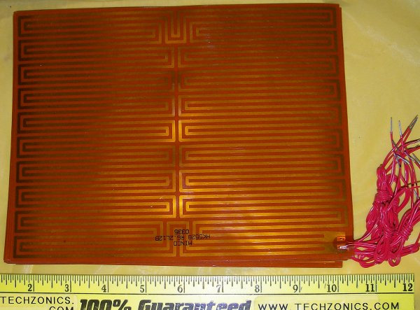
Here is an example of a pattern used in a commercial film heater:

enter image description here

Yours would have to jog around through-holes, but if you splurged on blind vias that could be minimized.

\$\endgroup\$
2
  • \$\begingroup\$ Thank you. I have chosen a proper thermistor. The current go through the traces is directly from a DC power source. So maybe I don`t need to consider about the magnetic field, right? \$\endgroup\$
    – billyzhao
    Commented Jun 27, 2015 at 2:54
  • \$\begingroup\$ Yes, it should only affect things momentarily when you switch it. You might want to add some hysteresis so it doesn't switch too frequently (or oscillate because of some small unanticipated feedback). \$\endgroup\$ Commented Jun 27, 2015 at 3:04
4
\$\begingroup\$

You can even make a long spiral of a thin trace in a few places and use those as thermal sensors. It'll require a bit of experimentation, but it can work very well to build a temperature controlled board like that. The thermal drift in resistance in copper is only 3.9*10^-3, so if you can make a 10 ohm trace at 20 degrees C, it'll be about 12.3 ohm at 80 degrees C. Certainly a detectable difference, but not the easiest.

(you could use the calculator at the bottom of this page)

You can also just put a few PTC or NTC modules on one of the surfaces :-) But that's less impressive/magic :-P

As @PlasmaHH suggests in a comment you should take care not to start out pumping energy into it, to prevent from large differentials from occurring. If you add low to medium amounts of energy to the middle layer that energy can have time to dissipate evenly.

You can help the dissipation of the energy by leaving copper in between the heating traces that can carry away excess heat from one spot without components to a spot with many. You can help it even more by putting the heating between two nearly solid power planes, but I don't expect that to be needed. The thermal conductivity of FR4 materials is already very decent as well.

Just don't take away any copper that you don't need for heating, that'll help a lot, and if you can connect those to a safe ground trace or plane: First of all that will conduct the heat away to that plane, which helps, but it also avoids resonances and such when you start PWM-ing the heater.

\$\endgroup\$
6
  • \$\begingroup\$ Nice idea using the traces as sensors - you can even combine the two and measure the resistance of the heating traces to determine how hot they are. \$\endgroup\$ Commented Jun 26, 2015 at 10:38
  • \$\begingroup\$ @NickJohnson Which you can do by the current you force, indeed, but it'd be a compound average effect over the length, unless you localise the heat production. That also has advantages if you can sacrifice a couple of extra pins on a controller, to allow you to locally heat more or less. \$\endgroup\$
    – Asmyldof
    Commented Jun 26, 2015 at 10:51
  • 1
    \$\begingroup\$ So do you mean my idea is practical? \$\endgroup\$
    – billyzhao
    Commented Jun 26, 2015 at 12:01
  • 2
    \$\begingroup\$ @billyzhao Translating Asmyldof's answer: "Yes, and here are some ideas how to make it better and avoid some possible problems." \$\endgroup\$
    – JRE
    Commented Jun 26, 2015 at 13:34
  • \$\begingroup\$ I would not recommend PWM-ing the heater, you would be inducing all kinds of electrical noise into your circuits. You need to calculate the amount of energy you need to maintain a given PCB temperature and apply a small DC for a very long time, to provide that energy. \$\endgroup\$
    – Guill
    Commented Jul 3, 2015 at 5:16

Your Answer

By clicking “Post Your Answer”, you agree to our terms of service and acknowledge you have read our privacy policy.

Not the answer you're looking for? Browse other questions tagged or ask your own question.