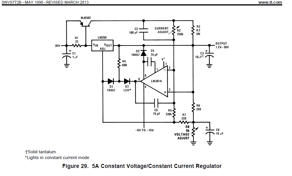
I take the circuit below given in a TI application note, and I have some questions about the way the circuit works:

The circuit is designed as a 5A constant current/constant voltage regulator. First I have examined the voltage loop, I found it to be composed of R6 and R8. This voltage divider sets the output voltage for the circuit.
When I come to the current loop, many questions arised:
- I understand that the PNP transistor used in paralell with the internal pass element of LM350 to share the output current since LM350 cannot supply 5A. But how does the circuit work in the current loop configuration, I did not get it because:
- To control the output current, we usually measure it by means of a sense resistor (shunt resistor). R3 may play that role, but I think only the current supplied by PNP transistor will be monitored by that.
- If we assume the OPAMP LM301A is used to monitor the current, how does it regulate the current? What is the purpose to put it in an integrator form by placing C5 between its inverting input and its output!
- What is the role of D1 and D2?
