You would prefer that a coupling capacitor have very low voltage across it at all frequencies of interest. A cheap electrolytic capacitor might have an ESR of 1-2 ohms which might vary by less than one ohm *(over the audio bandwidth**. The input impedance of a line in might be 10K. There's thus negligible voltage change (-0.002dB) which doesn't change much over frequency.
Other than leakage and noise/microphonics the characteristics of a coupling capacitor in an single-ended system are not very important- it is supposed to act as a 'short' so if it's a bit better or worse or slightly nonlinear short it's still part of a fairly negligible voltage change. Most of the signal appears across the input and almost nothing across the coupling capacitor. The capacitor inductance may start to have some small effect at >10,000Hz, but again that's not very important. Probably few, if any, human beings can tell the difference between a 10kHz sine wave and a 10kHz square wave.
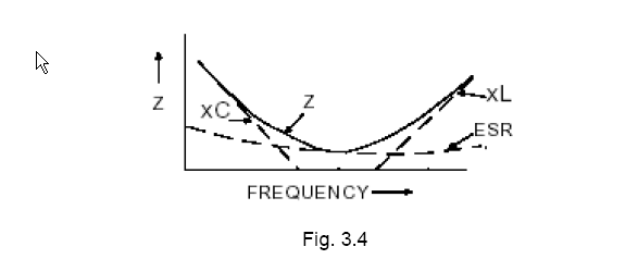
The overall impedance looks like the below from here. The minimum series impedance is at the resonance point (when it is just ESR). The audio frequency range will be in the area where Xc and ESR dominate and Xl just becomes important. Aside from the roll-off at the low end, it's all pretty negligible.

Filters are another matter- the capacitor characteristics such as voltage coefficient, temperature coefficient, dielectric absorption and so on matter a lot.

