6
\$\begingroup\$

Nowadays, I am trying to make a Caller ID project without using Caller ID ICs. Firstly, I have done a lot of research in Google to get information of phone lines and their electrical properties.

I have found and done:

  1. In my country Caller ID data is FSK modulated. And the name of the standard is Bell 202. In this standard there are two different frequency which are 1200 and 2200. As you know these frequecies are using to digitalize the data(1 and 0).
  2. Secondly, I write a C# program that demodulates any arbitrary FSK modulated signal. This program uses the Goertzel Algorithm and it fits like a glove for DTMF decoding and FSK demodulation. Basically, its output gives you the dominant frequecy in your reference frequecies(1200 and 2200 in our case) for your input signal.

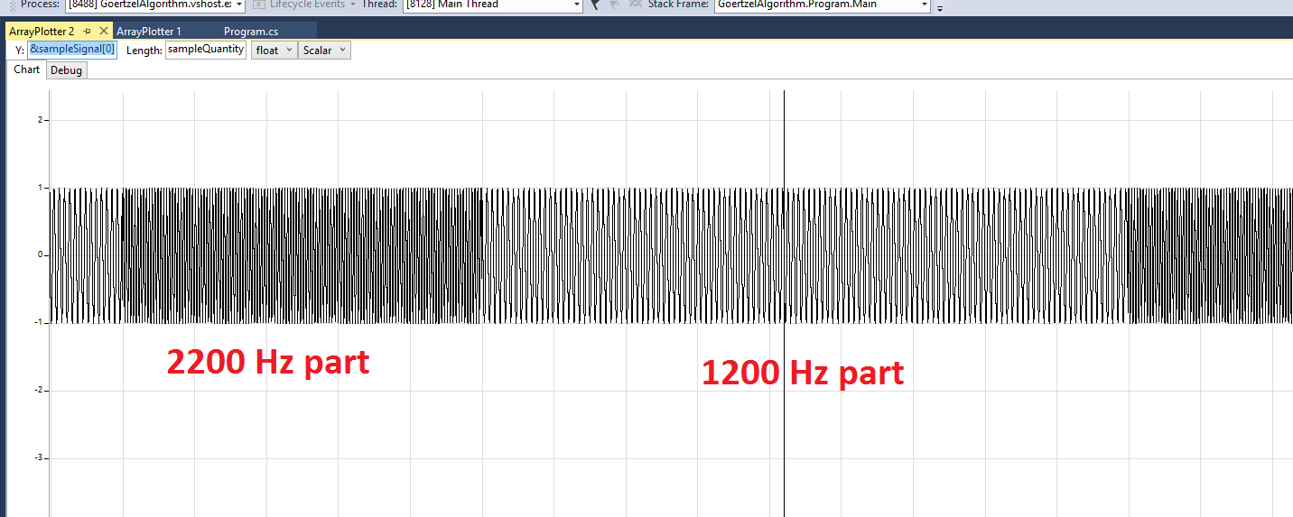
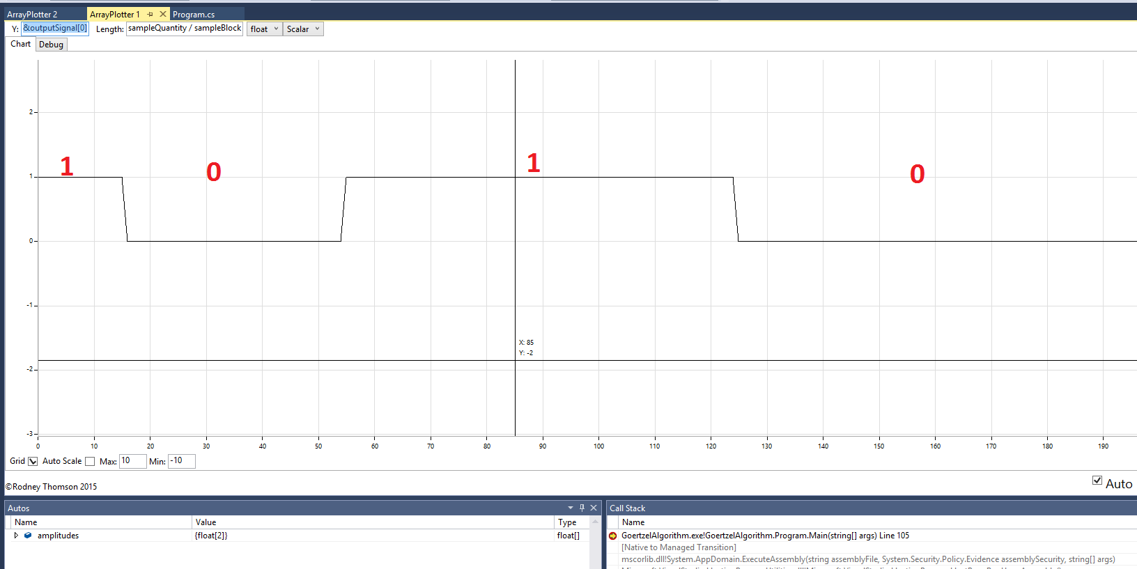
Here are some screenshots from code and output result.

Input: The arbitrary sin wave I have created to simulate the code

Output: The output for the input signal above

I will add the running code here later. The file link I have added the end of the page may not seen a non-dangerous file for some people like me:)

I think the first part of project done. But the real problem comes with second part for me. I do not have enough practical electronic skills and measurement tools(ossiloscope, common components etc.) to get phone line signal into computer. I look google and see that phone line has very high voltage -48Vrms to -52Vrms. I want to make a circuit that get the digitalized phone line signal to send it to the computer in the place of my arbitrary input. I found some application notes in Caller ID ICs datasheets and there are some circuitry and I think some of them is very appropriate for me. In this point I need to get some assistance to realize this circuit and project.

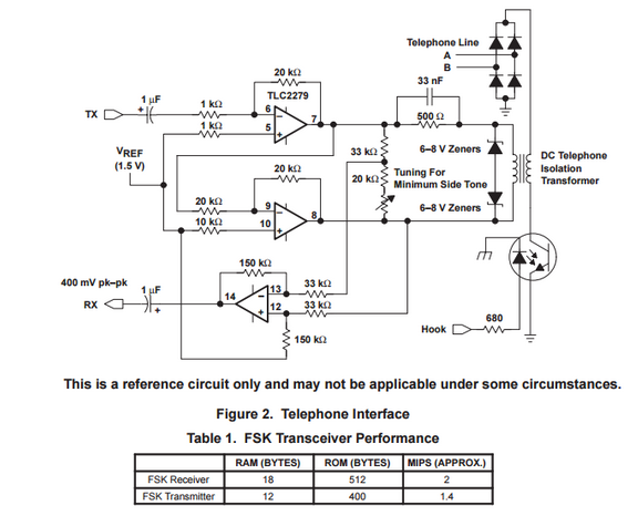
Here are some circuit that I think it is proper for my project. enter image description here
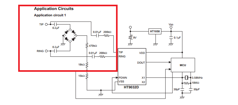
What is the output of the circuit in the red rectangle? Is it an appropriate signal for an MCU like Arduino or a for a PC?

What about that circuit? According to this paper. RX signal is 1.2V DC biased and 400mv p-p signal and it propably carries our data we want, right?

enter image description here

PS:I am adding the link of the code and screenshots for people intersted in.

http://www.filedropper.com/goertzelalgorithm

\$\endgroup\$
3
  • 1
    \$\begingroup\$ There is not a single reference to Caller ID in that TI document, you are just assuming it is fit for your specific purpose. You'll have to search for the Caller ID spec's in other documentation, not in a random application note that happens to use FSK modulation. But it needs to be said that I like your research efforts, it is a good way to learn things like this even if there is a chance that they may not work first time. \$\endgroup\$
    – jippie
    Commented Aug 5, 2015 at 16:54
  • \$\begingroup\$ Hi jippie. Thanks for your support. I will be sharing all the process done. Have a nice day \$\endgroup\$ Commented Aug 5, 2015 at 16:56
  • \$\begingroup\$ Also I think the 1.2VDC bias is for specifically for a 3V3 microcontroller as the MSP series. YMMV with other inputs. \$\endgroup\$
    – jippie
    Commented Aug 5, 2015 at 16:57

3 Answers 3

3
\$\begingroup\$

It's an old thread but in case you are still working on this, or anyone else is interested, there are 2 examples of completed Software based PSTN Telephone Caller ID projects here: https://forum.arduino.cc/index.php?topic=528459.0 or https://forum.arduino.cc/index.php?topic=490392.0 Both use a software AFSK demodulator to interpret the CLIP information which is send with the ring burst and include a schematic diagram and all software. One also even handles spam calls.

\$\endgroup\$
1
  • \$\begingroup\$ This answer is the solution for the project. I gave up after trying many things. Now cannot wait to try them. Thanks for your answer. \$\endgroup\$ Commented Feb 20, 2018 at 12:52
2
\$\begingroup\$

Two of the line look like they will carry the signal that you're after, the ones that connect to the topr-right corner of the IC with the series resistor and capacitor, but you cannot/shouldn't connect them straight to you PC without:

  • knowing the expected signal levels of the signal you are interested in, the inputs must happily accept the signal levels;
  • protect the input against ring voltage, which can be up to several 100's volts peak to peak;
  • protect against overvoltage as a result of eg. lightning in the neighbourhood;
  • an insulation transformer for galvanic separation of the phone line/PC. (You can often find those in old modems or telephone sets.
\$\endgroup\$
0
\$\begingroup\$

I suggest that while you are testing and proving your software and hardware you avoid the real telephone line with its high voltage issues. Use your computer sound card as the source for the DTMF tones and hook up to the stereo jack. Use this web page http://onlinetonegenerator.com/dtmf.html to generate the tones for you to prove that your design works. Once you have made progress with that you can look again at the caller ID on the real phone line.

\$\endgroup\$
2
  • \$\begingroup\$ Caller ID doesn't use DTMF, it uses a modulated digital signal that is sent in between rings. \$\endgroup\$ Commented Aug 5, 2015 at 15:37
  • \$\begingroup\$ Correct! we need fsk modulated signal and I can do it basically to change frequency of sin wave according to data. Now it is time to get phone line signal and make the code run on it. Thanks for suggest anyway. \$\endgroup\$ Commented Aug 5, 2015 at 15:43

Your Answer

By clicking “Post Your Answer”, you agree to our terms of service and acknowledge you have read our privacy policy.

Not the answer you're looking for? Browse other questions tagged or ask your own question.