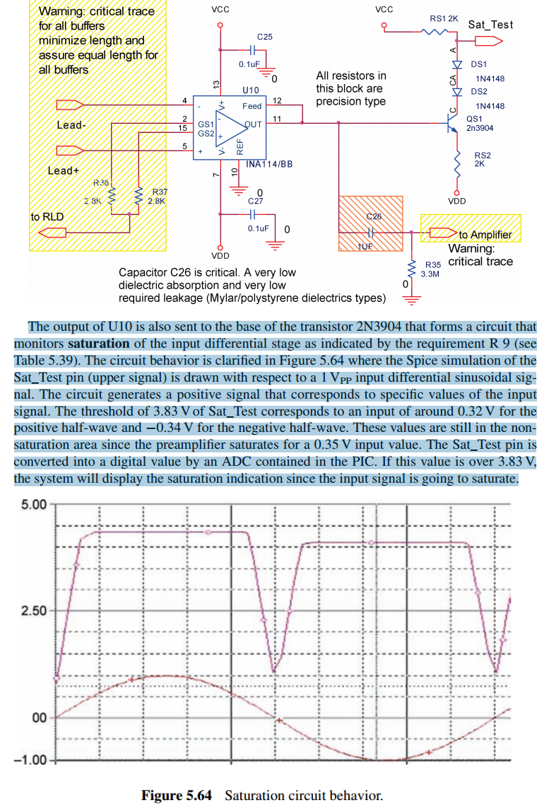
I'm trying to understand the behaviour of an NPN transistor and two diodes connected to the output of an instrumentation amplifier [image below]. The transistor appears to switch on when there is a negative voltage applied to the base, as well as when there is a positive voltage applied. Can anyone explain what is happening here?
I would also like to know how I could tailor this circuit to work with a different voltage range and different supply voltage, in particular, for +-1.4V input to base with a 3.3V supply.
Thanks.
The supply is dual rail +-5V and the instrumentation amplifier gain is just under 10.
The text and images are from the book "Medical instrument design and development: From requirements to market placements" by Claudio Becchetti and Alessandro Neri.

