1
\$\begingroup\$

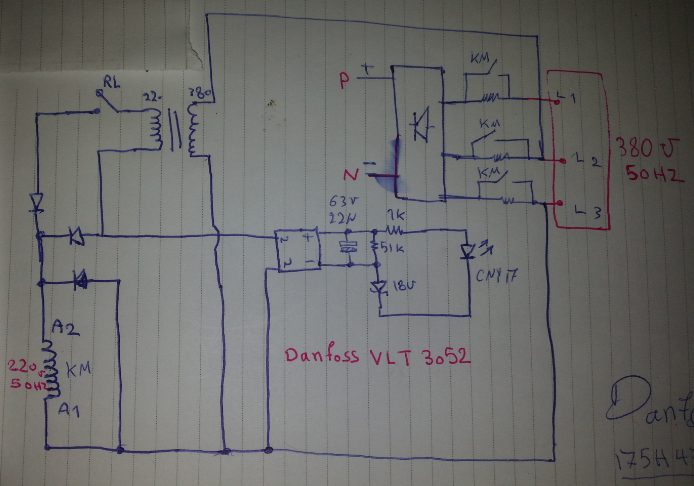
This circuit is a DC bus capacitor soft charge from a 3phase inverter. I've seen a lot of similar products but this one is a little strange and I'm curious how it works. I want to know why the transformer's output is rectified(I assume) knowing that the contactor works with AC.

\$\endgroup\$
6
  • \$\begingroup\$ @LorenzoDonati I think it is a part number Danfoss 175H leads to VLT's. \$\endgroup\$
    – jippie
    Commented Aug 15, 2015 at 10:59
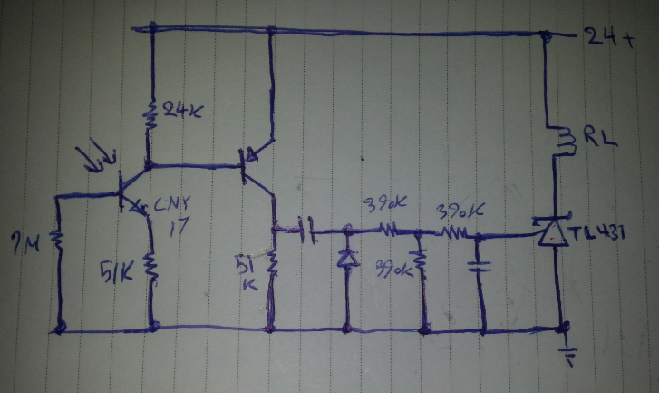
  • \$\begingroup\$ The lower circuit is pretty straightforward, it is a timer that will prevent KM from being energized for a moment. The actual soft start is in the top right quadrant: When switching on there are three resistors in series with the controller, then after the timer times out these resistors are shorted by KM contacts and the controller is at full load. Can you be a little more specific as to what part of the circuit you want to discuss further? \$\endgroup\$
    – jippie
    Commented Aug 15, 2015 at 11:29
  • \$\begingroup\$ The light for the CNY in lower circuit comes from the upper one. They're the same CNY. And the number in the first image is the Danfoss model number. \$\endgroup\$
    – BehzadSh
    Commented Aug 15, 2015 at 11:29
  • \$\begingroup\$ Either you have drawn it wrong or it won't work. \$\endgroup\$
    – Andy aka
    Commented Aug 15, 2015 at 11:45
  • 1
    \$\begingroup\$ THe two diodes at upper left are VERY unlikely to be correctly drawn. \$\endgroup\$
    – Russell McMahon
    Commented Aug 15, 2015 at 14:03

2 Answers 2

1
\$\begingroup\$

Perhaps there is a hidden center tap on the transformer secondary that connects to the circuit common (L3) through the lower primary lead.

A center-tap connection would answer another mystery about the circuit pointed out in another answer: Because of the series capacitor connected to the collector of the PNP transistor, the timer circuit can't energize RL indefinitely.

With RL initially open (and assuming a center tap), the hypothesis is that the half-wave-rectified DC applied to the contactor is not enough to pull it in. When the timer closes RL after the soft-charge period, both diodes can conduct, and the contactor sees the full-wave-rectified output of the transformer. The full-wave-rectified voltage closes the contactor. Finally, the timer allows RL to open (because of the PNP series capacitor), but the half-wave-rectified voltage is now sufficient to hold the contactor closed.

If this is how the circuit works, I'm curious about the operating margins. Under high-line conditions, the initial half-wave-rectified voltage could risk closing the contactor before it should close. However, doubling the average coil voltage between half-wave and full-wave rectification roughly quadruples the magnetic force, so good margins are plausible with a carefully selected transformer voltage. If margins aren't a problem, an advantage of this kind of approach is that it reduces static power consumption by de-energizing the relay and lowering the coil power of the contactor when the soft-charge cycle is complete.
\$\endgroup\$
0
\$\begingroup\$

The schematic around the left side of the transformer can't be correct. Please retrace that part of the circuit and make corrections.

It very much looks as if the contactor coil is driven with pulsating DC.

The capacitor in the middle of the bottom diagram looks not correct. I don't think that it is in series with the signal. Could you re-check that as well?

\$\endgroup\$
1
  • \$\begingroup\$ Thanks. I've checked the circuit many times. The reason I'm asking the question is exactly the thing you said. \$\endgroup\$
    – BehzadSh
    Commented Aug 15, 2015 at 15:23

Your Answer

By clicking “Post Your Answer”, you agree to our terms of service and acknowledge you have read our privacy policy.

Not the answer you're looking for? Browse other questions tagged or ask your own question.