0
\$\begingroup\$

I'm working on an inclass project, for a two-tone alarm circuit. The 3V source represents two AA batteries. We've implemented this successfully on a breadboard. The IC used for the Inverted Schmitt triggers is a 74HC14N. schematic
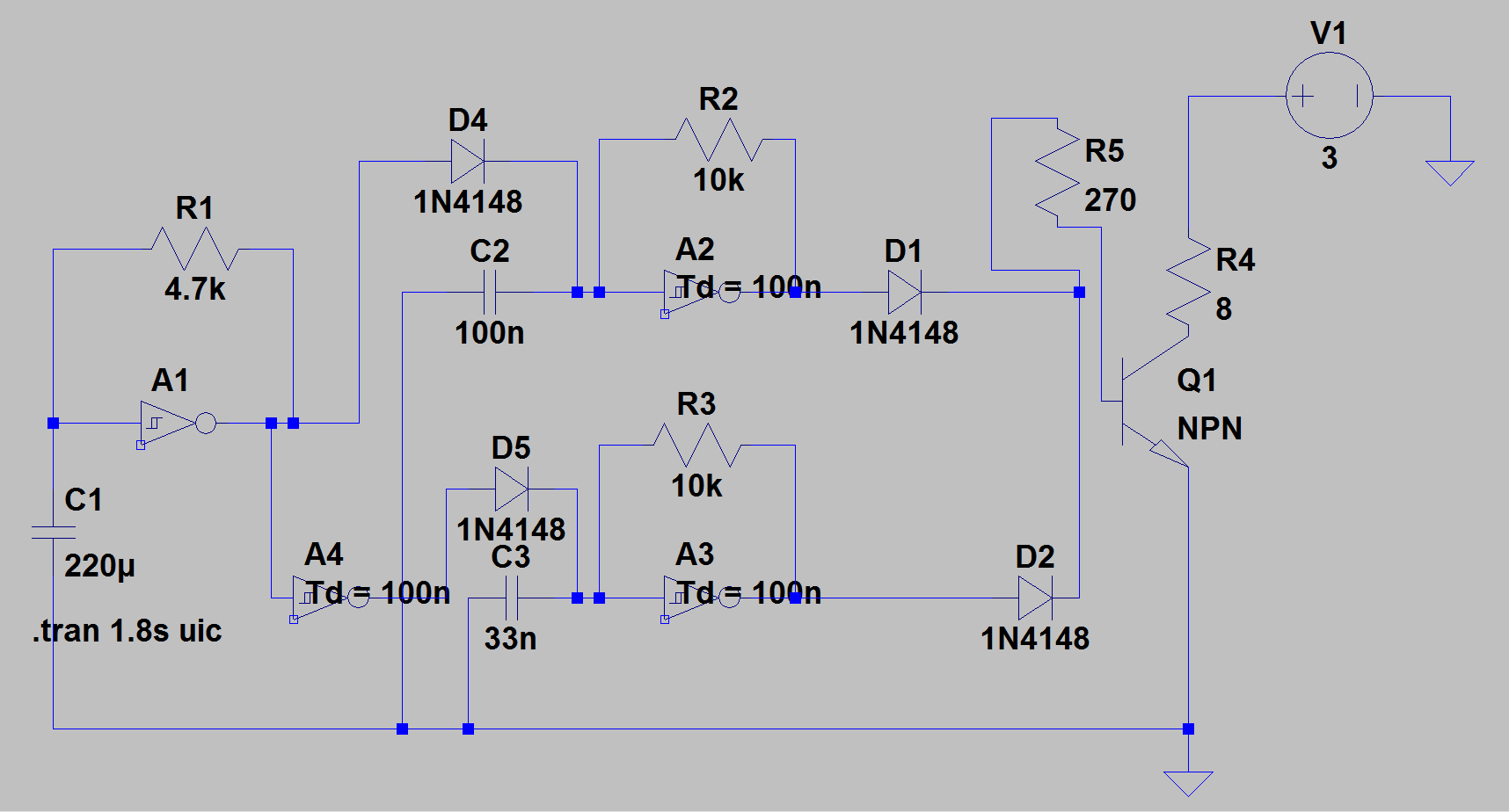
I've been hinted that there is an issue regarding current spikes on D4, but I can only see a very short initial spike...is this a major issue?

We have also been told that if there is not some base resistance, such as the one in R5, this will cause major issues with the transistor. We have implemented it without this R5 and it works as expected.

Any other comments or ideas on things to explore would be really appreciated.

I've seen this implemented with far fewer components, but we got to this point using our knowledge.

\$\endgroup\$
4
  • \$\begingroup\$ Look at the datasheets of the involved components and compare their SOA to what your simulation gives. If you already have implemented it, do the measurements and compare with the components SOAs. \$\endgroup\$
    – PlasmaHH
    Commented Sep 7, 2015 at 11:45
  • \$\begingroup\$ QUT Jack W? Enb245? If so, it's to limit current through the speaker which has a 250mW max power rating. You control your current gain with R5 through the transistor \$\endgroup\$ Commented Nov 17, 2015 at 12:45
  • \$\begingroup\$ Although Dave has edited this recently, the students are not aware that the RdsOn for 74HC' series rises to ~ 1k when the supply drops to 3V but is never specified due to the wide tolerance on Vt internally. Therefore there will not be enough current gain in a saturated Q1 to drive an 8 ohm load with "expected currents". It means some samples may oscillate but be low in drive current and others may not. The caps are far too big and R's too small. by orders of magnitude. \$\endgroup\$
    – D.A.S.
    Commented Jun 14, 2019 at 4:49
  • \$\begingroup\$ Furthermore removing R5 causes A2 output to only reach 1.2V instead of exceeding the VinH hysteresis threshold so it wont oscillate at all. They should have used the spare inverters to buffer the outputs. or scrap this poor design and start over with specs. \$\endgroup\$
    – D.A.S.
    Commented Jun 14, 2019 at 5:08

1 Answer 1

1
\$\begingroup\$

R5 controls the current gain through the transistor path, which allows you to control the current through the 8 ohm resistor at the end via bjt gate current equations.

If you were say, going to QUT and taking enb245. It would have been useful because the peizo speaker you have connected as that 8ohm resistor has a 250mW rating, so you can use R5 to limit the power delivered to the speaker.

\$\endgroup\$

Your Answer

By clicking “Post Your Answer”, you agree to our terms of service and acknowledge you have read our privacy policy.

Not the answer you're looking for? Browse other questions tagged or ask your own question.