1
\$\begingroup\$

I'm designing a tone control stage for an audio amplifier I'm designing. I'm receiving a mono signal that is fed into 3 filters:
Lowpass - 0:250 Hz
Bandpass - 250 Hz:4 kHz
Highpass - 4 kHz:infinity
(all theoretical obviously)

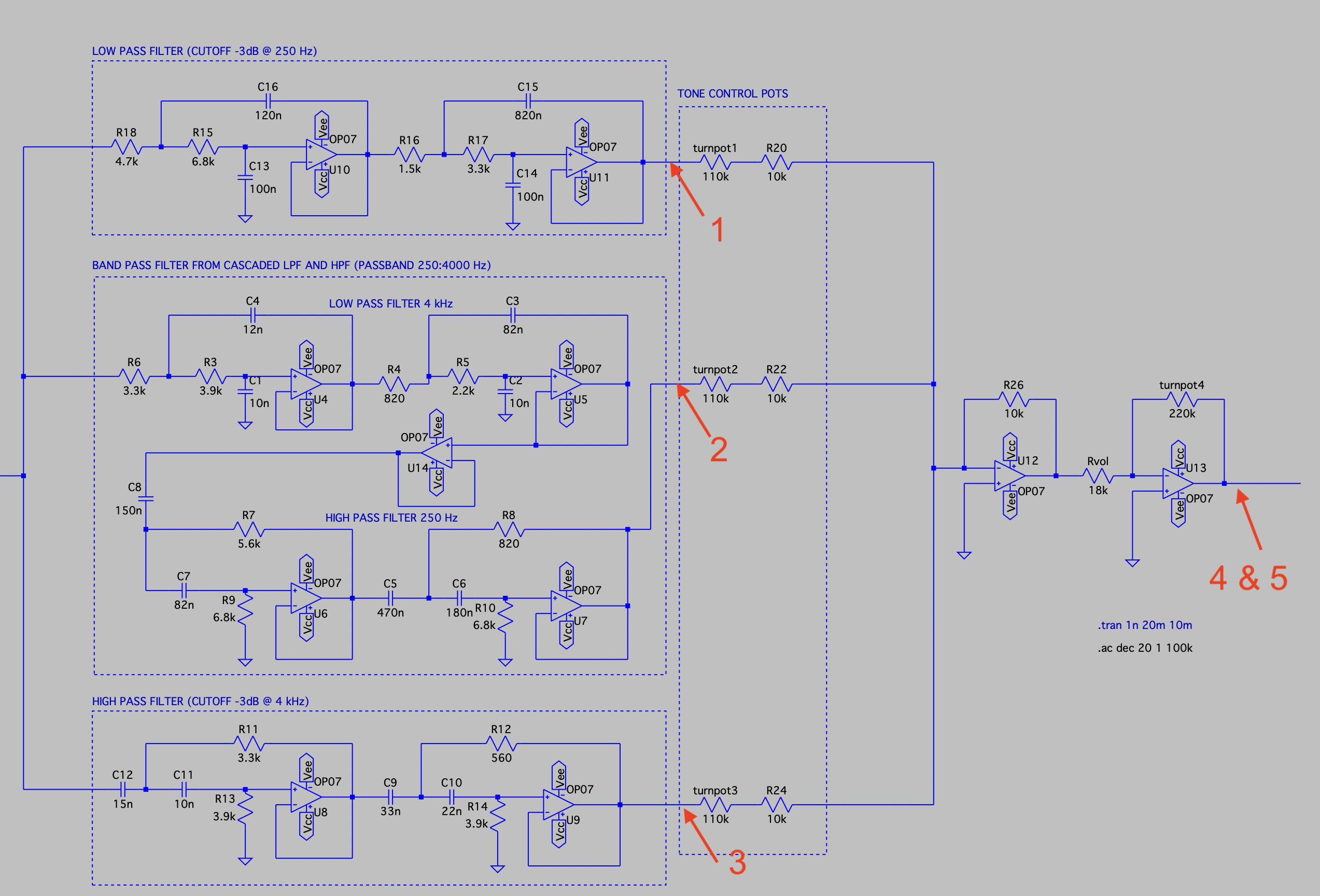
The filters are 4th order Butterworth designed using Sallen-Key topology. The bandpass is just cascaded LP and HP filters, as annotated in the schematic.

'My LTSpice Schematic'

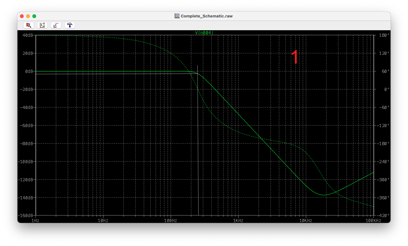
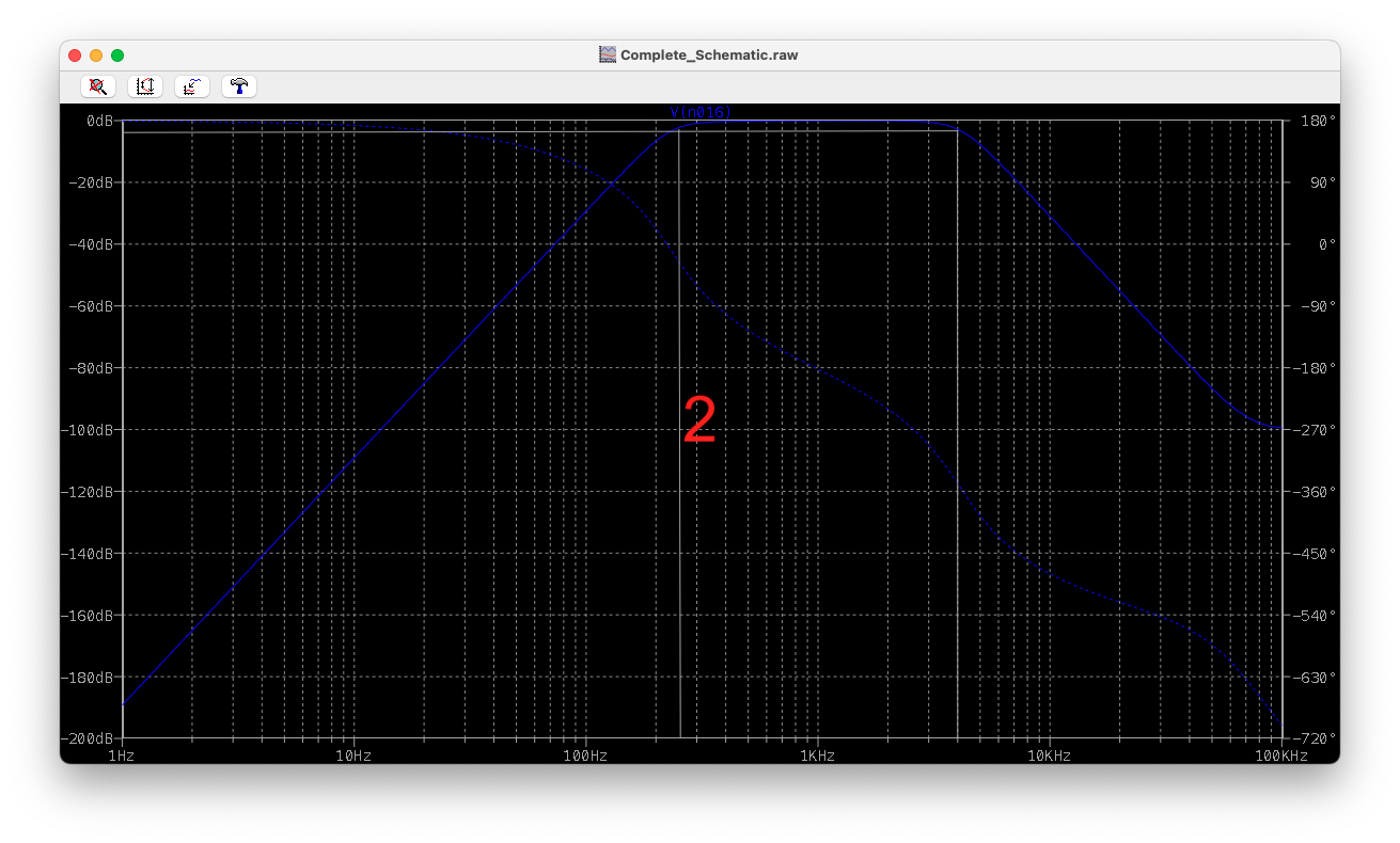
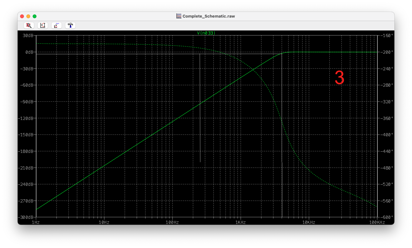
I've designed the individual circuits and have been simulating them, and am very happy with the individual filters' outputs. (see images)

Running the AC analysis shows I'm getting a very acceptable cutoff at my desired LPF (1), BPF (2), and HPF (3).

enter image description here enter image description here enter image description here

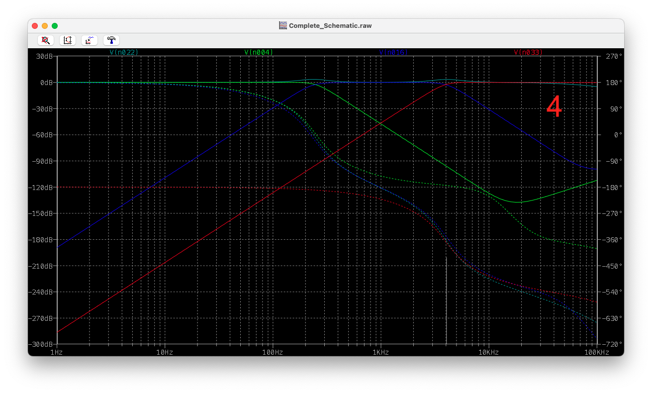
(4) shows the output after summing and volume control and that the signal it closely follows the filters' response.

enter image description here

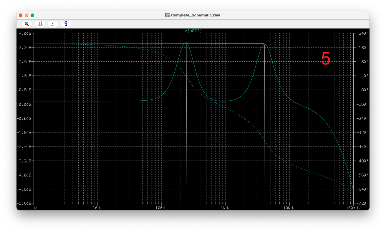
(5) shows the output signal zoomed vertically. At the frequencies 250 Hz and 4 kHz where I've set my cutoff points, the crossover between the two is causing pretty large spikes that will effect the audio quality. I'd like to minimise this difference to be at least below 2 dB, but I don't know where to start. In modifying the values at these ranges, the filters just become more inaccurate. I am wondering if the issue is phase related? The only solution I can think of doing is creating another stage on the LPF and HPF causing a steeper drop-off and thus lowering the superposition effect at the crossover frequencies, however, with these filters already being 4th order it seems pretty overkill.

enter image description here

Any help or guidance would be much appreciated, including any other faults in my design not specifically related to this question.

\$\endgroup\$
5
  • \$\begingroup\$ Did you use a software tool to design the filters? If so, please provide a link to it. \$\endgroup\$ Commented Aug 13 at 21:21
  • \$\begingroup\$ Is there a specific reason as to why you chose this way? I don't know whether this is a common method for a 3-band tone control circuit but why didn't you go for a Baxandall circuit or FMV (Fender-Marshall-Vox, not that accurate though and bands start to overlap as the control amounts change)? \$\endgroup\$ Commented Aug 13 at 22:10
  • \$\begingroup\$ Try filters with non-standard passband attenuation to get rid of the spikes. If you raise the attenuation from the default value of 3.01dB to 6.02dB, you will get amplitude dips instead of spikes at each crossover frequency. Use somerhing like ~5.5dB for Butterworth or ~4.5dB for Chebyshev type filters. The overall passband will not be perfectly flat around each crossover frequency but the spikes will be gone. \$\endgroup\$
    – Raonoke
    Commented Aug 14 at 2:24
  • \$\begingroup\$ @RohatKılıç I don't think this is a very common method but that's sort of the point, I don't want to follow some formula or common practice. I understand that passive tone control used in FMV and Bax. is treble cut. The only way to boost individual frequency bands is to use an active filter, whereas the passive circuits rather cut them. \$\endgroup\$ Commented Aug 14 at 7:59
  • \$\begingroup\$ @Raonoke Thanks, will give it a shot! \$\endgroup\$ Commented Aug 14 at 8:01

1 Answer 1

0
\$\begingroup\$

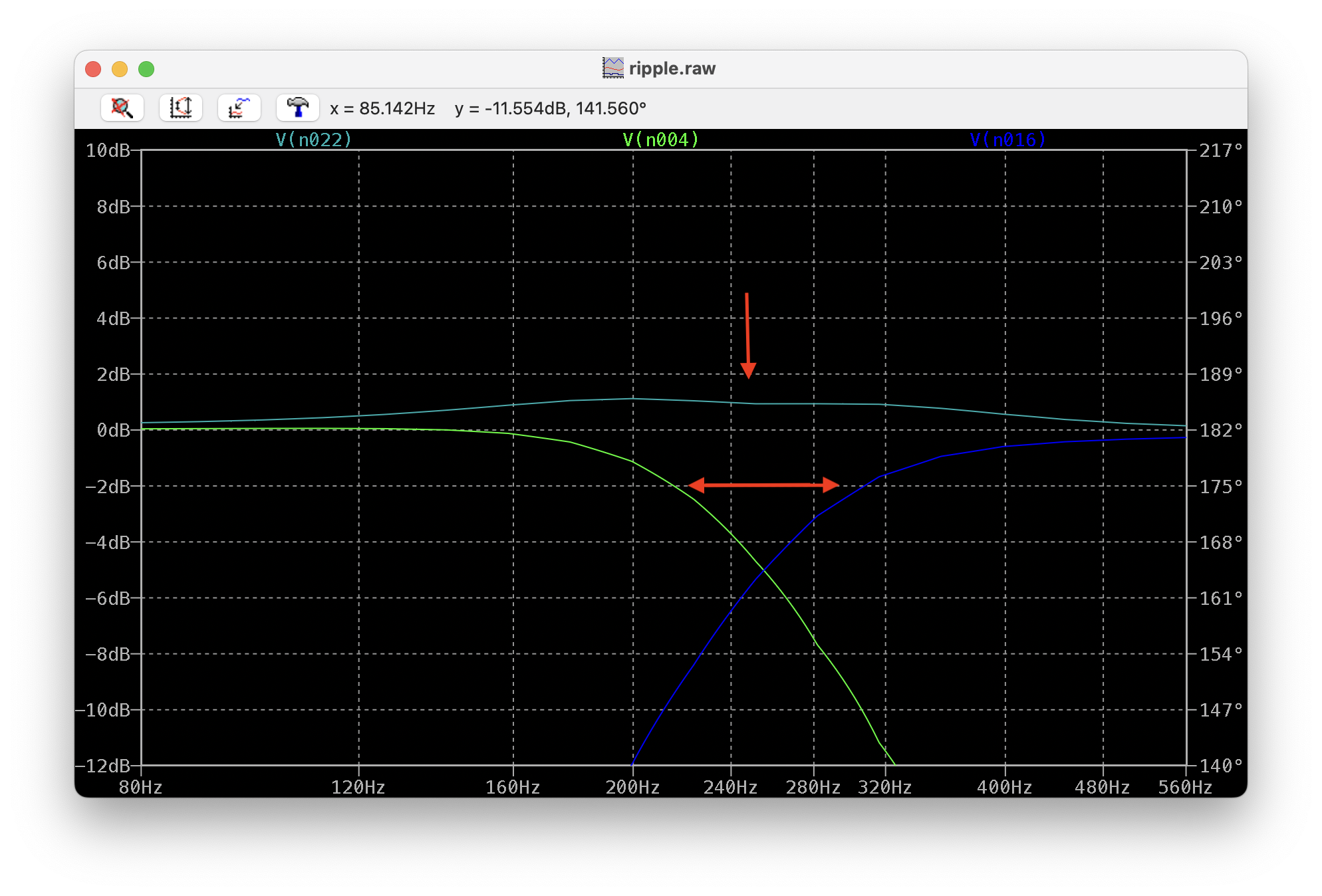
The best way I found to solve this was to slightly adjust my bandwidth parameters for each filter. The spikes are naturally caused by the crossover frequency superpositioning. Because of the logarithmic dB scale, you only need to slightly push your decreasing curves away from one another to get a noticeable reduction in the spike. Spike reduction The bandwidth narrowing effect is negligent in my case, so this sacrafice was fine.

\$\endgroup\$

Your Answer

By clicking “Post Your Answer”, you agree to our terms of service and acknowledge you have read our privacy policy.

Not the answer you're looking for? Browse other questions tagged or ask your own question.