0
\$\begingroup\$

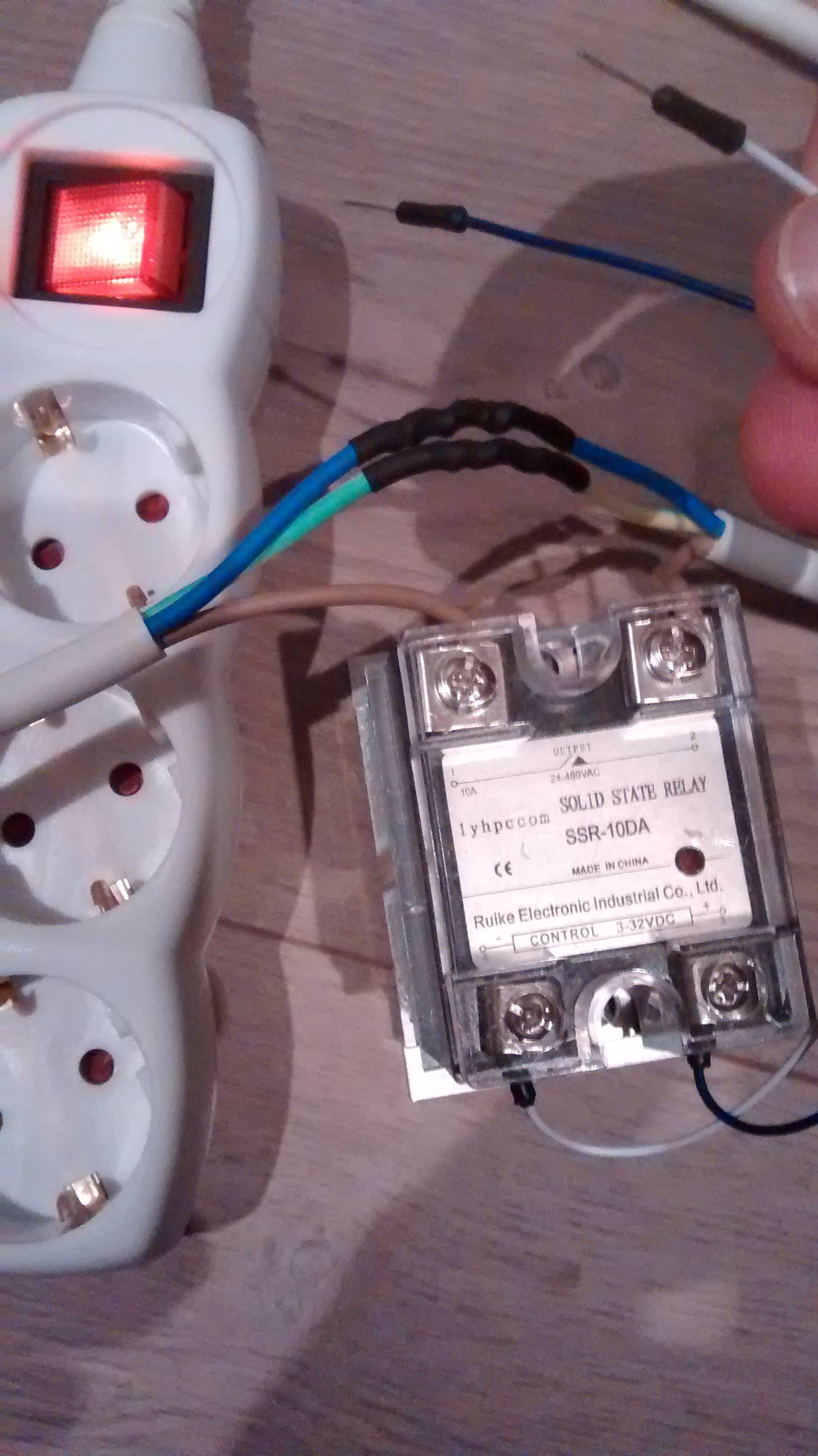
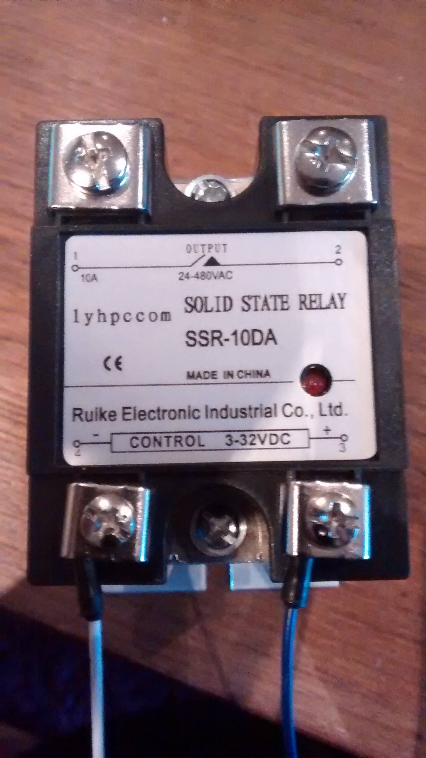
I have an SSR (pictured) that I intend to wire up to a European 220v appliance (in Norway) and a Rasberry Pi. It appears from this post that no diode is necessary (with an optional 1k resistor).

So then I would just take the 3.3v power, via a 1k resistor, to the GPIO pin to the SSR, then a ground back to the RPi?

SSR in question: enter image description here


Update:

After wiring things up, it appears the SSR has power regardless of whether there is a voltage over the control side (see pic). Any suggestions?

enter image description here

\$\endgroup\$

2 Answers 2

2
\$\begingroup\$

You can hook it up directly or with a current limiting resistor (to protect both sides from a faulty condition).

But you have to make sure that it will work correctly. So for this, you look up what kind of currents are needed to make the SSR trip.

The datasheet (if that's the correct one, I hope so), says it has a low tripping current of under 7.5mA. So 7.5mA should be the least current your Raspberry should be able to supply (then it will work with every SSR-10DA).

As you have 3.3V, the current limiting has a maximum value of 440\$\Omega\$. But that would mean that you would have a short in the SSR, which you probably won't have. So another important value is the minimum ON voltage. Which is given as 2.4V.

So you have 3.3V, 7.5mA current and at the terminal you need at least 2.4V, so 0.9V/7.5mA = 120\$\Omega\$ as the maximum resistance, which would leave no room for tolerances and stuff.

So if you want to put a resistor there, go for 100\$\Omega\$ maybe, probably lower, but if the SSR input shorts it won't protect your GPIO from an overcurrent (16mA per pin maximum from what I found).

Another note: The 3.3V rail from the RPi seems to be very limited as discussed here: What is the maximum current the GPIO pins can output? So probably it would be better to use a transistor as depicted in your linked post to switch it from the 5V rail.

\$\endgroup\$
10
  • \$\begingroup\$ That datasheet does not seem to be related to the product shown.. at least from my first look. I agree with the use of an NPN transistor to drive the control input, because then the SSR could be replaced with a mechanical relay as well, and it would still be powerful enough to operate that as well. \$\endgroup\$
    – KyranF
    Commented Oct 2, 2015 at 16:49
  • \$\begingroup\$ @KyranF have a look at page 3, the model number matches, the basic specs on the relay are also there. \$\endgroup\$
    – Arsenal
    Commented Oct 2, 2015 at 16:52
  • 1
    \$\begingroup\$ Ah yes, the "SSR-10DA". Okay then, that's fair. I agree that it will need some significant current (the 7ma trip current) just to turn it on, probably all the zener diodes and internal LEDs etc which consume current while it's "on". The safest thing which also prevents any inductive loads which the SSR is switching from affecting the microcontroller is the NPN transistor and resistors shown in the diagrams of the device datasheet. \$\endgroup\$
    – KyranF
    Commented Oct 2, 2015 at 19:56
  • 1
    \$\begingroup\$ @ryanjdillon yes, you will place a current limiting resistor between the base and the GPIO, basically the transistor acts as a current amplifier, with a beta of 30, you would need just 0,25mA flowing from the GPIO through the base, so you can easily put a 1kOhm resistor there and it should be fine. \$\endgroup\$
    – Arsenal
    Commented Oct 4, 2015 at 8:46
  • 1
    \$\begingroup\$ @ryanjdillon have you tried it with a real load? I had those tiny lights from a multiple plug light up because neutral and phase were interchanged once (that was a strange thing, but the wiring in that house was a nightmare) \$\endgroup\$
    – Arsenal
    Commented Oct 29, 2015 at 23:20
1
\$\begingroup\$

From your link a NPN transistor shall be used for buffereing, RPi GPIO can't drive the SSR directly, therefore you can use the same circuit as depicted in that link, the only thing you can leave is the freewheeling diode.

\$\endgroup\$
1
  • \$\begingroup\$ So leave out the diode? I'm understanding things a bit more now with Arsenal's answer. I certainly would like to protect against overcurrent on the GPIO pin - and prevent anything exciting happening on the SSR connected to 220V. \$\endgroup\$ Commented Oct 4, 2015 at 8:44

Your Answer

By clicking “Post Your Answer”, you agree to our terms of service and acknowledge you have read our privacy policy.

Not the answer you're looking for? Browse other questions tagged or ask your own question.