A problem like this depends mostly on the material of the ball. There are a number of sensors you could use depending on the type.
Off the shelf method:There are ultrasonic range finders which could tell you how far away the ball is at any given time, but if its made of something that can distort sound waves this might limit your accuracy, plus using a sonic device would mandate that your ball is going significantly slower than the speed of sound. These ultrasonic range finders can be found at many electronics stores and sites as they are often integrated with arduino projects.
As for your method of using 2 sensors, it could work, but your accuracy is going to be limited by a lot of factors, and if the ball doesn't travel just right, you could miss the sensors all together. Still, if you wanted to do this I would recommend getting 2 infrared diodes, and 2 infrared receiver diodes.you can put the reciever on one side of the box and the and transmitter on the other, then do the same in the back. you should be able to detect the ball via a drop in the voltage generated by the receiver diode when the ball passes through it.
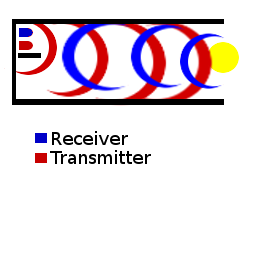
A nearly off the shelf but high accuracy method:Use an IR diode pointed outward from the box and then use an IR receiver diode also pointed outward from the box to measure the intensity of the IR light reflected back form the ball as it moves into range. This method has the advantage that you have a lot more data points since you can determine the intensity of the reflected light as the ball comes in and calculate the speed from that. you can emit the light at a particular frequency to remove background IR contamination which yields much better results, you may run into problems though if your ball is very hot or is a very good absorber of infra red light. This method would require an IR transmitting diode and an IR receiving diode. commonly available at electronics stores.
Whichever method you use you will probably need a microcontroller to emit your waveform from the diodes, measure the incoming waveform from the diodes and compute the speed.
Here is an image of the basic setup. Notice you can add a small shelf beneath the diodes so that it is just a slit that is too small for the ball to hit it.

Also note that the exact intensity of the light reflected back will depend on the material at some distance r one material may reflect back IR with intensity A and another with intensity 2A, however the since you are computing speed, you are only interested in the change in intensities so as long as there is enough IR reflection to detect the material should not matter too much.
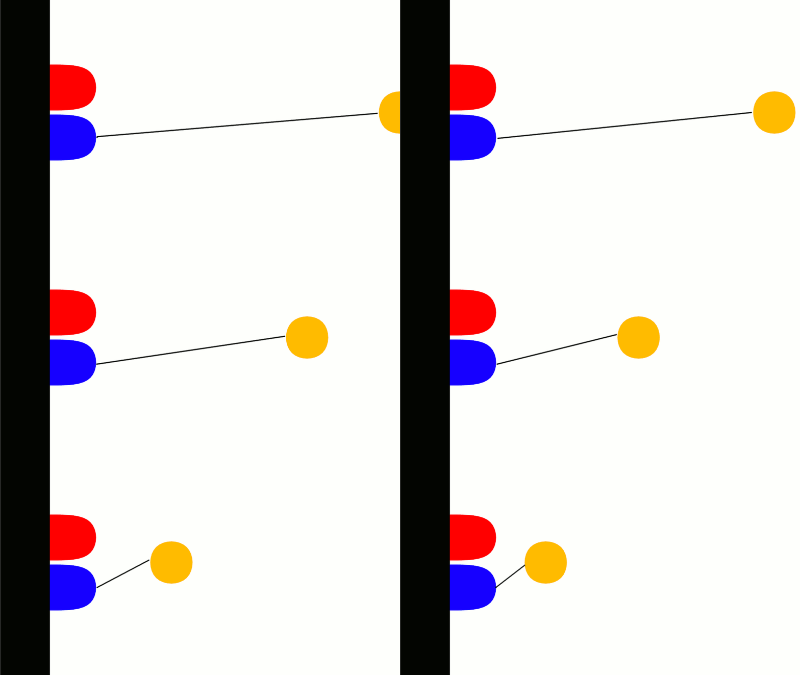
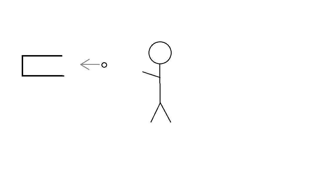
Edit: This is a one dimensional sensor, meaning it will only tell you 1 dimension of the velocity. Since you want to measure the speed of a ball that is in the box then, you have to ask yourself "What do I mean by the speed of the ball?" An actual ball thrown in to a box is going to come in at some non-perpendicular angle to the sensor, and will have some acceleration vector which acts to change its velocity. Not to mention drag forces. So there are a couple things to notice here. In this idealized animation of the ball entering the box, the black line shows the velocity vector that the sensor actually measures. As you can see, the closer the ball gets to the sensor, the more the velocity in the direction of the sensor is going to be diminished. When the ball sufficiently far away from the sensor, the velocity vector is sufficiently indistinguishable from a straight line.
 Now with that understanding, there are a couple ways you can correct for this error if it gets to be outside of your tolerance. You can move the LEDs further back, maybe even outside the box altogether and just leave a slit in the back of the box where the light can penetrate. This method of correction allows you to make the difference between the total velocity and the measured velocity as small as you need for the application.
A purely numerical method to correct for this would be to collect your intensity samples for the entire window in which the ball entered the box and drop the samples at the beginning (when it was too far away) and the samples at the end(when it was too close) You will have fewer data points with this method, but it will still be fairly accurate.
The most accurate way however would be to use 4 transmit/receive diode pairs inside the box (i.e. 1 on top, 1 in the back, and 1 on each side) You could then obtain the relative position of the ball in 3 dimensions using a technique called trilateration This method obviously has some more computational overhead, than the others, but should still be practical to implement on a single microcontroller. You would need to use different carrier frequencies for each diode pair though to distinguish it from the others.


