6
\$\begingroup\$

Let's suppose I have a voltage of 60 Hz, containing distortion due to 3rd, 5th and 7th harmonics (180Hz, 300Hz and 420Hz).

Is it possible to phase shift the 3rd harmonic (for example) without shifting the rest of the signal ? If yes, how and using what ?

EDIT : Adding more information just like Sean Asked

i read this article : Harmonic interactions of multiple distributed energy resources in power distribution networks, ELSEVIER Journal

basically what they did, is taking under consideration the phases of the harmonics :

In a systems with multi harmonic sources, the injected harmonic current from each source add vectorally. Therefore, it is crucial to study the impact of each harmonic source phase angle on the total harmonic distortion.

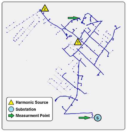
Here is the network Model they used :

NETWORK MODEL

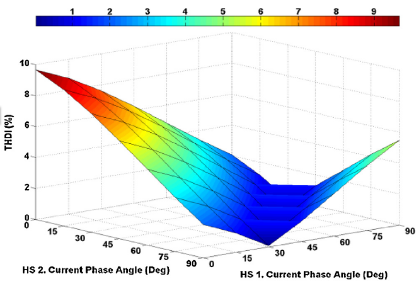
So a number of harmonic simulations were performed with the phase angles steps for both harmonic sources (1 & 2) being varied as follows: (0◦, 15◦, 30◦, 45◦, 60◦, 75◦, 90◦) to the : 3rd, 5th, 7th, 9th and 11th harmonics. the result of the THD according to each combination is in the following Graph :

THD According the variation of phases

Now, i saw that for some combination of Phases (ex :75° to Source 2 & 45° to Source 1) the THD is reduced because the harmonics canceled each other, without any harmonics mitigation technique, so i was wondering if it is possible to create an algorithm to compute the right combination of phases for N harmonics sources in a way they cancel each other and than apply those phases to each harmonics in each source, to obtain a minimum THD without any effort of mitigation. of course in the real life not all harmonics have the same phase, so the phase shifting must be different for each harmonics rank, and this is why i asked my question at the first place

\$\endgroup\$
3
  • \$\begingroup\$ This is a confusing question. Any filter will change the output impedance of any voltage you might have. I do not think that such behavior is desirable. More info is needed. \$\endgroup\$ Commented Oct 31, 2015 at 3:03
  • \$\begingroup\$ I have a concern about the necessity for this arrangement; having seen a number of harmonic mitigation methods and phase shifting arrangements for power control, I suspect having the answer for this question may lead you down a bumpy road to nowhere. If you update your question with the design specifications, particularly, why you want this done, we might be able to point at something better. It would also give a sense of the order of magnitude, which is important in implementing a solution. \$\endgroup\$
    – user39962
    Commented Oct 31, 2015 at 5:41
  • \$\begingroup\$ If someone came up with such a method it would be worthy of at least academic publication if not patent[s], so really, if you expect someone to invent one for you here... you overestimate the importance of SE token points in real life. Now it is possible something like this was researched already by someone... But I doubt it's something commonly/actually used in practice. Google Scholar is your friend. \$\endgroup\$ Commented Nov 14, 2015 at 16:35

4 Answers 4

3
+50
\$\begingroup\$

Conceptually, what you seem to be proposing seems to be something like passing the entire current of a branch of the grid through a system that extracts specific harmonic currents and injects them back into the grid with a different phase relationship to the fundamental to cancel harmonics originating in another branch. Passing all of the current of a branch through any system would seem to be less efficient than some kind of active or passive filter that would handle only one or several specific harmonics.

A similar concept would be to have the major harmonic generating sources vary their waveform creation strategy in a way that would tend to cancel each other. I found a paper related to that, but I made a mistake in trying to save it. I will try to find it again and post a link later.

Added reference information re above:

Armstrong, Matthew; Atkinson, D.J.; Johnson, C.M.; Abeyasekera, T.D., "Low order harmonic cancellation in a grid connected multiple inverter system via current control parameter randomization," in Power Electronics, IEEE Transactions on , vol.20, no.4, pp.885-892, July 2005 doi: 10.1109/TPEL.2005.850949 Abstract: In grid connected multiple inverter systems, it is normal to synchronize the output current of each inverter to the common network voltage. Any current controller deficiencies, which result in low order harmonics, are also synchronized to the common network voltage. As a result the harmonics produced by individual converters show a high degree of correlation and tend to be additive. Each controller can be tuned to achieve a different harmonic profile so that harmonic cancellation can take place in the overall system, thus reducing the net current total harmonic distortion level. However, inter-inverter communication is required. This paper presents experimental results demonstrating an alternative approach, which is to arrange for the tuning within each inverter to be adjusted automatically with a random component. This results in a harmonic output spectrum that varies with time, but is uncorrelated with the harmonic spectrum of any other inverter in the system. The net harmonics from all the inverters undergo a degree of cancellation and the overall system yields a net improvement in power quality. Link

Here is a newer article by some of the same authors as the article you linked:

Arghandeh, R.; von Meier, A.; Broadwater, R., "Phasor-based approch for harmonic assesment from multiple distributed energy resources," in PES General Meeting | Conference & Exposition, 2014 IEEE, vol., no., pp.1-5, 27-31 July 2014

Here is an article about measuring harmonics including phase information:

Chakir, M.; Kamwa, I.; Le Huy, H., "Extended C37.118.1 PMU Algorithms for Joint Tracking of Fundamental and Harmonic Phasors in Stressed Power Systems and Microgrids," in Power Delivery, IEEE Transactions on, vol.29, no.3, pp.1465-1480, June 2014

\$\endgroup\$
4
  • \$\begingroup\$ Please Sir find this paper, i'll be waiting for it, \$\endgroup\$ Commented Nov 13, 2015 at 16:33
  • \$\begingroup\$ you completely got what i want to do, can i have more details about the second part of your answer please "A similar concept would.... tend to cancel each other", specially when you say : vary their waveform ! what do you mean ? \$\endgroup\$ Commented Nov 13, 2015 at 16:34
  • 2
    \$\begingroup\$ That 1st paper has a free preprint/copy from its authors: ncl.ac.uk/eee/assets/posters/PV-papers/… Their solution is basically to randomize the harmonics generated by each inverter, so that on average they are uncorrelated. \$\endgroup\$ Commented Nov 14, 2015 at 16:38
  • \$\begingroup\$ @RespawnedFluff : at least something to read about. Fancy but complicated way to eliminate the harmonics. You would require a boost converter from grid (you don't have PV arrays) and then invert back to grid with synchronization. Quite complicated, not for experimenting, if goes wrong your IGBTs are fried, as well the facility will run down. \$\endgroup\$ Commented Nov 14, 2015 at 18:44
0
\$\begingroup\$

You could use a filter tuned to 180Hz that feeds into a phase shift, then have that feed through another 180Hz filter back into the rest of the signals. That way only the 180Hz portion makes it into the phase shifter.

Also as seen in comments below, a 180Hz notch filter would bee needed to filter out the 180Hz from the un-shifted portions of the signal.

\$\endgroup\$
3
  • \$\begingroup\$ I think you missed an important part of this idea. In the main signal path you would also need to put a notch filter that blocked the non phase shifted 180Hz signal. \$\endgroup\$ Commented Oct 31, 2015 at 2:46
  • \$\begingroup\$ Ah yes, that would be quite necessary. \$\endgroup\$
    – Daniel
    Commented Oct 31, 2015 at 2:57
  • \$\begingroup\$ I suspect that there would be quite a lot of unexpected effects due to the non-ideal nature of any implemented filter. However you may find that a real-world notch and pass filter at 180Hz will already cause some amount of phase shifting. I would not like to the the guy tasked with implementing this. \$\endgroup\$
    – KalleMP
    Commented Oct 31, 2015 at 10:32
0
\$\begingroup\$

Since the phases are shifted by 120 degrees, the first solution is to install a 3 column transformer. The 3rd order harmonics are all in phase, because 120*3=360, thus the flux from 3rd harmonics will collide and cancel in the 3 column transformer. Now you would need a second ring transformer with all 3 phases + excitation coil, where fluxes from 3 phase system will cancel each other while you can use a synchro generator with phase locked loop to inject the 3rd harmonics back into grid with different phase angle.

OK. What about this hypotesis:
you have fundamental frequncy V1*sin(wt) and other two phases: V1*sin(wt+120) and V1*sin(wt+240).
The 3rd harmonic is V3*sin(3wt) all of them are in phase.
The 5th harmonics V5*sin(5wt+5*120) . 5*120=600=600-360=240, other phases have 240 shift which makes them separated by 120. 240+240=480, 480-360=120. The 7th harmonics: 7*120=840, 840-720=120, again we have 120 phase shift in phases.

Now if you build a big toroid transformer with 3 windings + 1 extra winding, you don't have to insert the transformer in between, only attach parallel. You will get that the flux of 1st + 5th +7th will cancell out, the only remaining flux in transformer you get is the 3rd, and you get the secondar voltage in that extra winding. Now make a short circuit or add a resistor, the 3rd harmonics will be cancelled out at that specific point and you'll get a standing wave.

Further you can use a fluxgate, and feed the extra winding with current source such that flux in the transforme is cancelled.

\$\endgroup\$
3
  • \$\begingroup\$ my problem is that i can't use that (Transformers or coils), i need to do that in power-electronics ! what you think ? \$\endgroup\$ Commented Nov 13, 2015 at 16:20
  • \$\begingroup\$ what i am trying to build is a dynamic system that treat the harmonics i'm targeting so i can't put any static element if you know what i mean ! \$\endgroup\$ Commented Nov 13, 2015 at 16:36
  • \$\begingroup\$ Well I didn't know that, also I don't have access to the article. But, you can't simply connect in parallel a device that will "eat" the harmonics from the grid. You can inject the same harmonics, but then you get standing wave bouncing from one source to the yours portable source and beyond both ends. \$\endgroup\$ Commented Nov 13, 2015 at 17:16
0
\$\begingroup\$

Electronically inject a 3rd harmonic 180 deg. out of phase of equal magnitude to cancel the original. Then inject the 3rd at the angle and magnitude desired. This will have to be done with brute force, i.e., a fairly powerful generating device since the grids are "stiff". The generator logic circuitry must also detect the phase of the fundamental as a datum point (obviously).

\$\endgroup\$

Your Answer

By clicking “Post Your Answer”, you agree to our terms of service and acknowledge you have read our privacy policy.

Not the answer you're looking for? Browse other questions tagged or ask your own question.