1
\$\begingroup\$

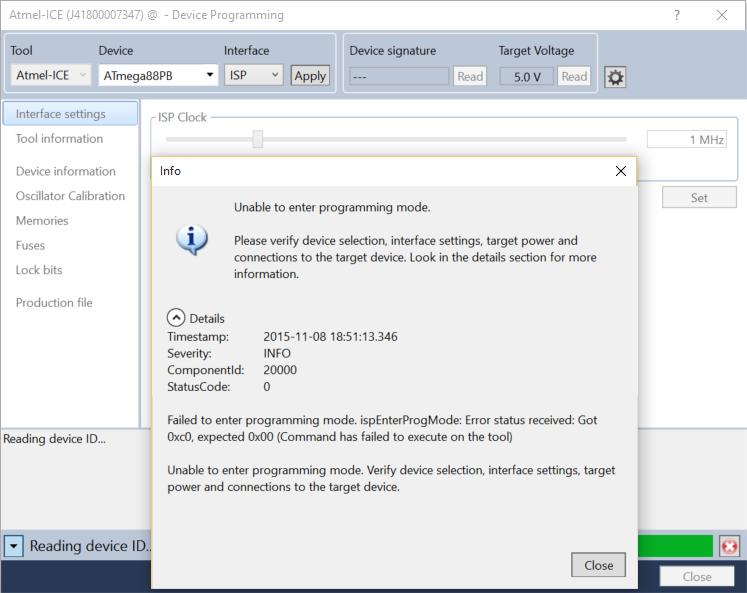
I have an ATMega88PB on a PCB which won't enter programming mode after changing the fuse settings to EXTFSXTAL_16KCK_14CK_0MS. Prior to this, the AVRISP MkII was able to communicate with the microcontroller (I've since switched to an Atmel ICE which still isn't able to communicate). Atmel Studio error
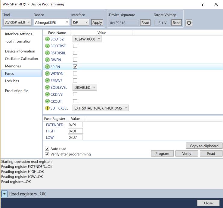
In case there are any doubts that I have changed other fuse settings incorrectly, here is a screenshot of the fuses prior to programming. Fuse settings
I find this confusing because the oscillator appears to be running fine - if I had programmed the incorrect fuse setting (e.g. ext clk) then I would expect the oscillator to be disabled to save power. As you can see this isn't the case, with the oscillator running just slightly under 20MHz.

XTAL2 waveform: XTAL2 Waveform

XTAL1 waveform: XTAL1 Waveform

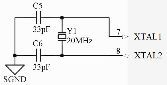
Here is the schematic for the oscillator circuit: Schematic
I've tried programming the device at every available speed and still haven't had any luck. I also tried feeding in a clock signal from a working AVR's CLK0 pin unsuccessfully, and have tried 18pF load capacitors in place of the 33pF indicated in the schematic.

What else can I try to get this microcontroller running again?

\$\endgroup\$

1 Answer 1

2
\$\begingroup\$

Your low fuse register is 0xD7. That equals 0b1101 0111 in binary.

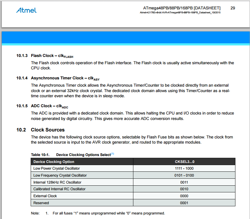
Looking at the data sheet the lower 4 bits are responsible for the clock. This correlates to

CKSEL3 = 0, CKSEL2 = 1, CKSEL1 = 1, CKSEL0 = 1.

From the data sheet this is not a valid setting, but it may be set to a low frequency crystal. The two similar valid settings are 0b0100 and 0b0101, they are both for a low frequency oscillator. Try replacing the 20MHz crystal with a 32.768kHz crystal.

An expected frequency and actual frequency mismatch may result in the processor not starting.

If that does not work, you may have to use parallel programming to recover the chip. Parallel programming does not require a working crystal and provides a clock externally.

Here is a screen capture of the data sheet. enter image description here

\$\endgroup\$
10
  • \$\begingroup\$ I'm not at a computer at the moment so I can't check, but is it possible that the fuse register shown by atmel studio is the old fuse settings it has detected prior to writing the new fuse? (In the screenshot, SUT_CKSEL has been changed but not yet written). \$\endgroup\$
    – bhillam
    Commented Nov 9, 2015 at 3:02
  • \$\begingroup\$ Page 27 of the datasheet says CKSEL3...0 = 0111 - 0110 corresponds to full swing crystal oscillator so I'm not sure why you think it's an invalid setting. Further, SUT1...0 and CKSEL0 = 011 corresponds to crystal oscillator, BOD enabled. (startup time 16k CK, +19CK from reset) and finally CKDIV8 = 1 means clock division is disabled. These are the fuses I have intended to program so I don't see the problem. \$\endgroup\$
    – bhillam
    Commented Nov 9, 2015 at 12:25
  • \$\begingroup\$ @bhillam I'm not sure what data sheet your working from, where did you get it? I got this data sheet from Atmels web site. Pictured is page 30. The oscillator setting 0111 is not listed. \$\endgroup\$
    – vini_i
    Commented Nov 9, 2015 at 12:53
  • \$\begingroup\$ I appear to have a preliminary datasheet. imgur.com/ID8x0TR not that it should matter since Atmel Studio should have the correct fuse settings (I didn't type in the hex field, I chose them in the GUI). \$\endgroup\$
    – bhillam
    Commented Nov 9, 2015 at 16:54
  • \$\begingroup\$ @bhillam So what is exactly in the HEX fields? Because your screen capture shows 16kCK_14CK_0MS which is not a setting listed in the data sheet. \$\endgroup\$
    – vini_i
    Commented Nov 9, 2015 at 17:15

Your Answer

By clicking “Post Your Answer”, you agree to our terms of service and acknowledge you have read our privacy policy.

Not the answer you're looking for? Browse other questions tagged or ask your own question.