0
\$\begingroup\$

Here is my task:

enter image description here

How to solve this? I'm confused because of only one input in opamp.

Edit:

Here is solution:

enter image description here

enter image description here

But I'm still confused why is there only one input to opamp

\$\endgroup\$
4
  • 1
    \$\begingroup\$ Here's a hint - how do you make a non-inverting amplifier with gain A from a single op amp? \$\endgroup\$ Commented Nov 19, 2015 at 18:56
  • 2
    \$\begingroup\$ To answer the confusion, that's not an opamp, it's an amplifier. You can make one using an opamp, as WhatRoughBeast suggests. \$\endgroup\$
    – user16324
    Commented Nov 19, 2015 at 22:01
  • \$\begingroup\$ Thanks for comments. We are studying opamps right now so I looked on that triangle as opamp instead of some "general" amplifier . I got A=6.7 \$\endgroup\$
    – hari
    Commented Nov 19, 2015 at 22:35
  • 1
    \$\begingroup\$ Yes - A=6.7 is correct. There are two othermethods for calculating. Either you can set the pole Qp to infinite:Qp=SQRT(R3/R1)/(6.7-A). Or you can set the loop gain of the feedback system to unity (oscillation condition). \$\endgroup\$
    – LvW
    Commented Nov 20, 2015 at 8:54

3 Answers 3

1
\$\begingroup\$

Consider the gain block "A" a non-inverting op amp configuration:
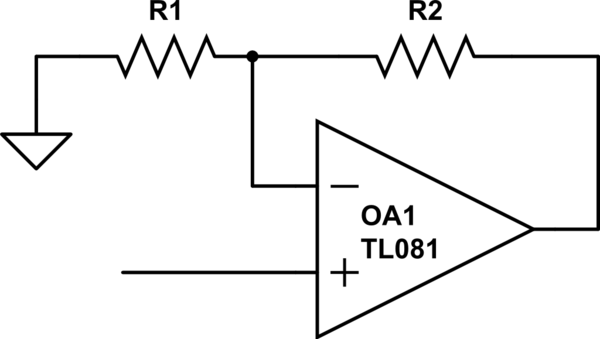
schematic

simulate this circuit – Schematic created using CircuitLab

A = 1+R2/R1

Then see this link for analysis of the filter:

Generalized Sallen-Key architecture analysis

\$\endgroup\$
0
1
\$\begingroup\$

Compare a 3rd order BJT sallen key filter with its op-amp equivalent: -

enter image description here

Sorry about it being a 3rd order filter but the principle is just the same. The BJT has a voltage gain of about 1 from base to emitter so treat the transistor as a gain block. If the gain increases, to keep the same type of response C2 has to lower and the other values have to increase to keep the frequency (and Q factor) the same.

It doesn't matter what is inside the gain block at all.

However, for this circuit to oscillate you have to ground the input and what you will find is that it oscillates at exactly the same frequency as a wien bridge oscillator with a gain of 3 when R1=R2 and C1=C2
\$\endgroup\$
1
  • \$\begingroup\$ @hari my asssumption about gain is that R1=R2=R etc. so maybe plug that into the equations as a means to simplify, after all it's still a sallen key with that simplification. \$\endgroup\$
    – Andy aka
    Commented Nov 19, 2015 at 23:47
1
\$\begingroup\$

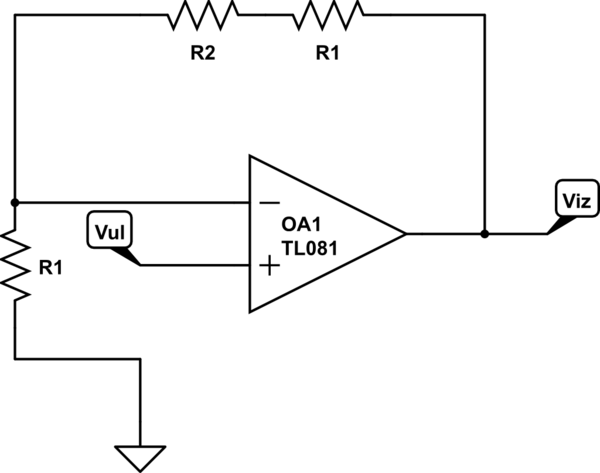
schematic

simulate this circuit – Schematic created using CircuitLab

Think it as like this schematic above. In the figure the opamp is demonstrated is like this. If you do the calculations you will see that you can put this instead of the gain block over there. However, it may would appeal the answer a little bit.

\$\endgroup\$
0

Your Answer

By clicking “Post Your Answer”, you agree to our terms of service and acknowledge you have read our privacy policy.

Not the answer you're looking for? Browse other questions tagged or ask your own question.