I'm back again with another headache of my own creation. It seems I'm constantly learning things the hard way.
Straight to the point questions:
I've noticed that my reverse voltage protection mosfet interacts with another p-mosfet switch in a bad way (yikes!). Does making the mosfets identical help with this interaction / do I want the switch to be more / less capacitive than the other?
I've made four copies of this design. One "works" and the others (that are in my opinion much more cleany routed) don't. Can sloppiness in soldering ever contribute to system performance?
Are there any easy ways to tell if a microcontroller is browning out vs resetting? (I'm thinking just scope the reset line / add a cap and see if it goes away?)
How I got here:
I'm making microcontroller switch boards. The design utilizes three mosfets: 1: Reverse voltage protection (p-mosfet) 2/3: n-mosfet / p-mosfet pair to turn on a 12V rail.
Here is the full diagram of the circuit:
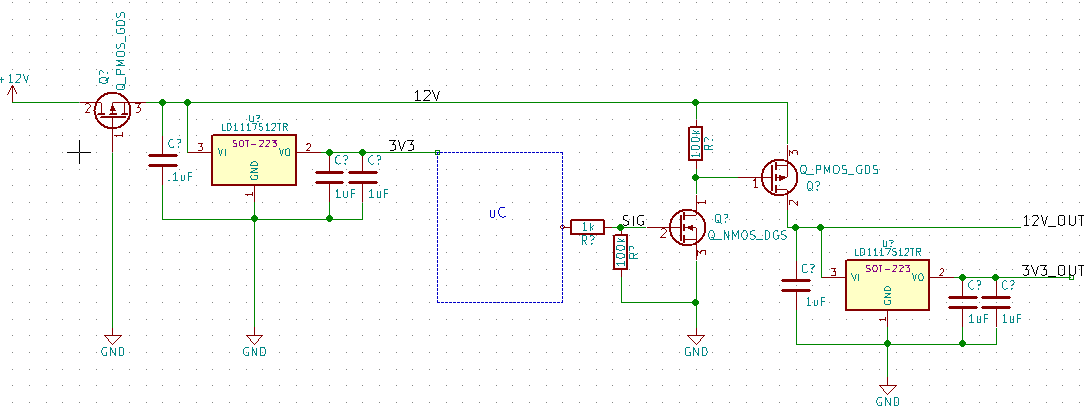
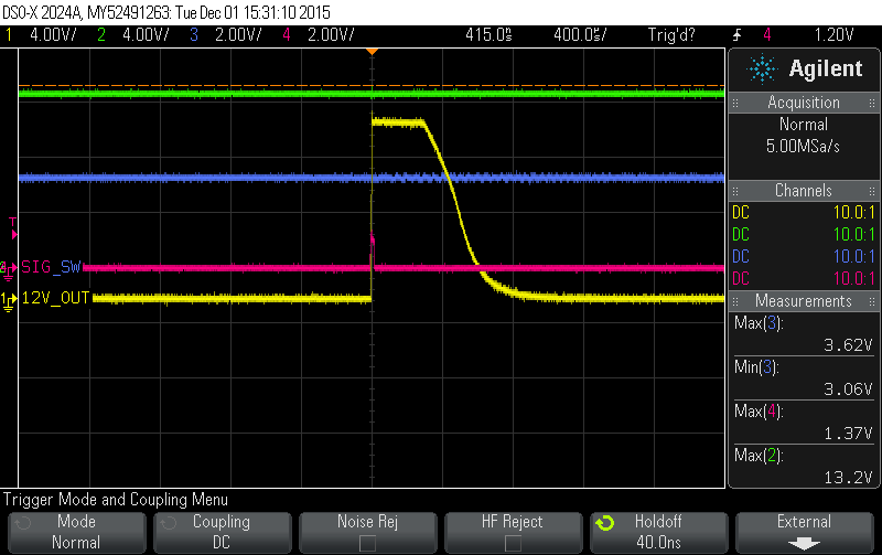
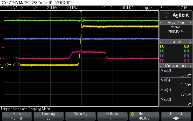
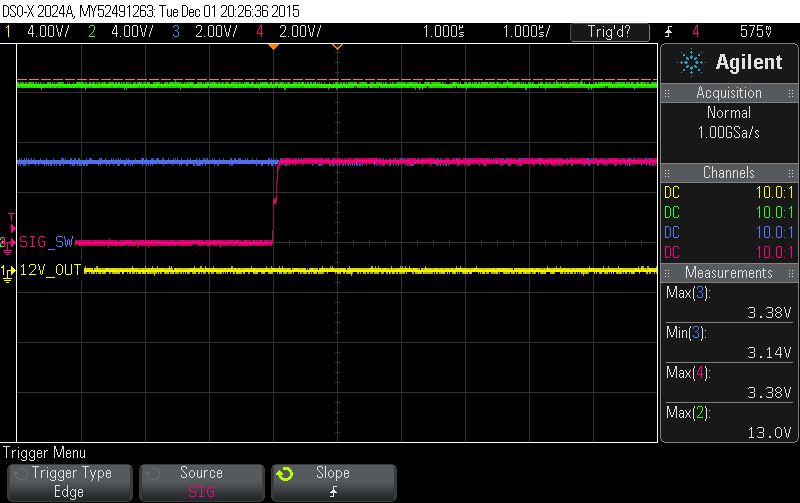
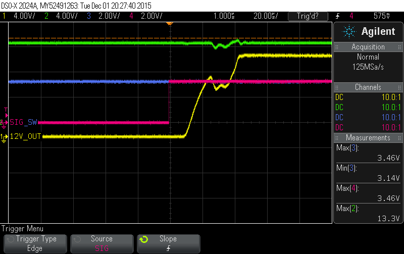
It seems like a simple circuit! I have used this type of circuit all the time (minus the reverse voltage protection). I figured everything would be aok. I constructed one, and it worked as expected. All good, right? So I made three more. None of the new ones work. The microcontroller resets when the switch is thrown (brownout?). After some head scratching I got out the oscilloscope and attached the leads to the 12V rails after each mosfet, the 3v3 rail after the first regulator, and the flip signal to the n-mosfet gate:
Looks innocent enough. ENHANCE!
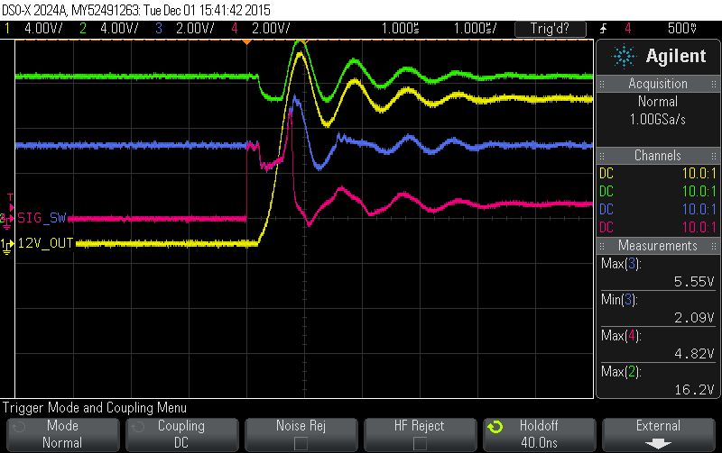
Uh oh. Is that a wiggle? ENHANCE!
Great. So I have a HUGE ripple going through my system. That needs to get fixed, right? I'm assuming this is part of the problem. (4V overshoot on the 12V... and a 3v3 ramping to 5v5... ouch). The 5.5v might significant because the microcontroller is rated for 1.8-5.5V? I know the controller shuts down if it's below 2v7. I'll change the brown-out level and see if that helps, but figure I should address the ripples head on.
I've researched the options.
1. Put a cap on my reset line (2V might be reading as logic low?)
Put larger caps on v_out for regulators. Currently I have the recommended 2uF, but it's not looking like it's enough?
Slow down the turn-on:
I plan on going with swapping the n-mosfet with a transistor (and maybe an rc circuit to drive as well). It's a battery operated circuit, so I'd like to save current (hence the n-mosfet). I'll watch the spec's for the mosfets to make sure I don't fry them on the way up, but this is a once/day thing so they have plenty of time to cool. Are there any tips / things I'm overlooking?
Also one other thing: The first circuit I built has WORSE swings (on the 12V rail) but seems to hold it's own / doesn't reset. I'm unsure of whether the reset is because of brownout, or because of the reset switch (I will add those pictures soon). The reset area is a little bit of a maze, so maybe the capacitance of the wiring is helping out? Any thoughts on this?
Many many thanks as always. Matt
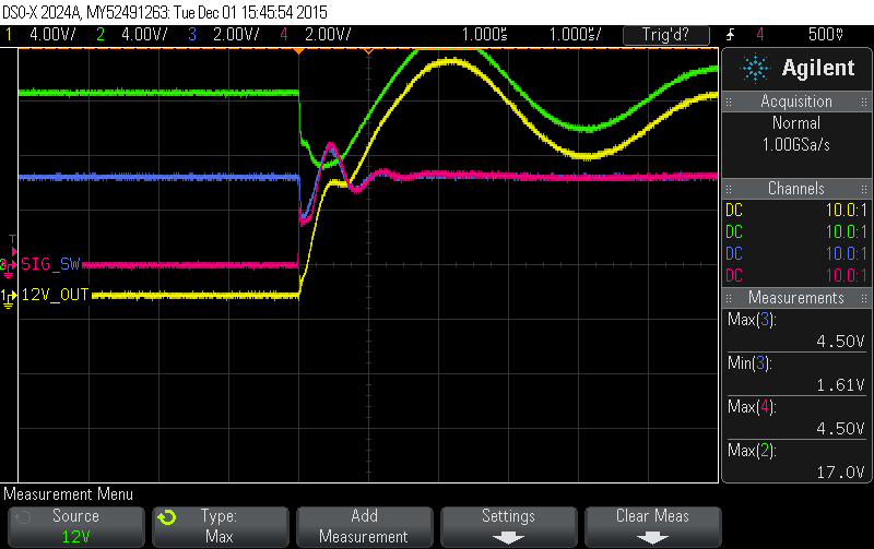
UPDATE: Sure enough, sometimes you gotta slow down. I'll let the data speak for itself:
I put a 100k resistor on the gate of the large mosfet. Slowing that down prevented squeezing the system all at once. Great response. Clear as night and day. I'm going to get started on chapter 2 of horowitz. Really should get a solid grasp on this stuff. Thanks jp!

