1
\$\begingroup\$

I am using this mosfet driver Intersil HIP2101. I have soldered a bootstrap capacitor to HB and HS of 100nF, a standard 100nF for supply stabilization and a 100kOhm resistor to HS and VSS. Now If I apply a PWM signal of 3.3Vp-p 200khz 50% duty cycle this is my signal:
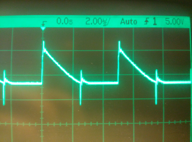
enter image description here Why is the voltage from t(0-ton) decreasing? The IC is meant for operating as a half bridge driver but I only have one PWM generator. Is this the problem or does it have another cause?

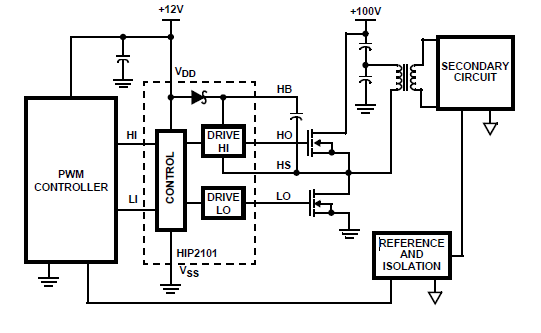
Schematic:

enter image description here

\$\endgroup\$

2 Answers 2

1
\$\begingroup\$

You should read up on how the bootstrap circuit works in order to understand if it is causing problems in your design. Obviously you suspect this already...

Typically you need to be alternately energizing and grounding that bootstrap capacitor to push the charge through the diodes in the bootstrap circuit. By removing the low-side switch, you are not providing a prompt switch transition that goes through Cboot and draws current from the input...

Story short, you need a high-side MOSFET switch that can provide its own bootstrap bias voltage without needing to be connected to the output switching node.

\$\endgroup\$
8
  • \$\begingroup\$ I did remove the low side switch but instead soldered a diode. I transformed it into an asynchronous buck converter. This is a recommendation of my supervisor. The problem is that I don't know if the IC expects and reacts only on 2 switches. \$\endgroup\$
    – Weaverworm
    Commented Dec 3, 2015 at 15:52
  • \$\begingroup\$ Yeah I guess that should work. But you could include that important piece of information in your question. What else are you leaving out? \$\endgroup\$
    – Daniel
    Commented Dec 3, 2015 at 15:54
  • \$\begingroup\$ Wait no. That would only work in CCM. In DCM, the switching node will float up to the output voltage, and the top-side transition will (potentially) not be adequate to charge the bootstrap cap. \$\endgroup\$
    – Daniel
    Commented Dec 3, 2015 at 15:55
  • \$\begingroup\$ Yeah I don't understand exactly what you mean, but I think you're on it now. One important piece of info I forgot is that the voltage difference between HB and HS is not 12V (as expected, I think) but 6V. This is tested with just the IC not the buck converter setup behind it. You have any clue why the voltage there is less than expected? \$\endgroup\$
    – Weaverworm
    Commented Dec 3, 2015 at 15:59
  • \$\begingroup\$ Do you know what CCM and DCM mean in switching converters? \$\endgroup\$
    – Daniel
    Commented Dec 3, 2015 at 16:02
0
\$\begingroup\$

The IC is meant for operating as a half bridge driver but I only have one PWM generator

Then I'm not surprised you see what you see. Try driving it correctly.

\$\endgroup\$
4
  • \$\begingroup\$ That's my problem. I don't have access to two waveform generators with configurable dead time (for the low side switch) nor have I access to two configurable PWM signals coming from any other microcontroller, processor, FPGA source. Can anyone explain this behavior or is it impossible? \$\endgroup\$
    – Weaverworm
    Commented Dec 3, 2015 at 15:50
  • \$\begingroup\$ Bootsrapping requires that the top and bottom MOSFET devices are fitted and driven regularly with PWM. If you can't do now what you want to do then why are you attempting to do this test? Why not wait until you have the signals ready to use? \$\endgroup\$
    – Andy aka
    Commented Dec 3, 2015 at 15:52
  • \$\begingroup\$ Good point. By configuring the buck converter in an asynchronous way my supervisor thought it a good idea to understand and test the converter. Should I just solder the low side switch and then first get the PWM signals ready? \$\endgroup\$
    – Weaverworm
    Commented Dec 3, 2015 at 15:54
  • \$\begingroup\$ If you have the top device fitted then it might work because of a the parasitic diode in the low device but temporarily ground the gate to the source or there'll be smoke within seconds. You'll still need a load though. \$\endgroup\$
    – Andy aka
    Commented Dec 3, 2015 at 15:57

Your Answer

By clicking “Post Your Answer”, you agree to our terms of service and acknowledge you have read our privacy policy.

Not the answer you're looking for? Browse other questions tagged or ask your own question.