3
\$\begingroup\$

I want to make an astable multivibrator with a 50% duty cycle that can be tuned with a potentiometer for generating sound, so accuracy is desired.

My first thought was to build the standard one with transistors, but that requires 2 resistors that control the mark and space separately.

enter image description here

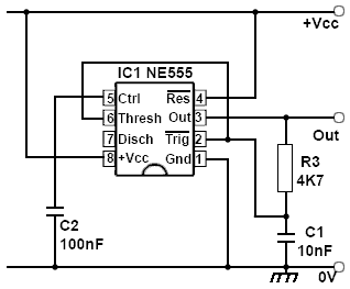
Second thought was to use a 555 timer. I made the below circuit with a pot for R3. The circuit claims to have a 50% duty cycle and a frequency of 1.4/RC. Except it satisfies neither of those claims.

555 circuit

It only has 50% when Vout=Vcc, which is not the case. This thing does not go rail-to-rail. It's also not linear. If I halve the resistance, the frequency is less than doubled.

So the question is if there is such a circuit that truly has a 50% duty cycle and where the frequency is linearly dependant on the RC time? where frequency closely matches \$f=\frac{k}{RC}\$

[edit] To clarify what I meant by linear. Any sort of sensible/relevant/simple relation between resistance and frequency will do. But I was thinking of something that actually does \$f=\frac{1}{RC}\$.

The point is that I want to connect multiple potmeters with buttons to make sort of a keyboard. Now if you press 2 buttons you get parallel resistance. I'm hoping that those parallel resistances will turn out to be nice harmonics. This is why I mentioned that 2 buttons of the same resistance don't quite make an octave(double frequency) with the 555 circuit.

[edit2] I'll put some values for the relaxation oscillator here, which is expected to do \$f=\frac{k}{RC}\$, but just like the above 555 circuit this does not seem to be the case. \$C=10^{-6}\$

  • R=4.01k, f=136
  • R=3.13k, f=191
  • R=2.05k, f=290
  • R=1.30k, f=452
  • R=0.95k, f=602
  • R=0.56k, f=915
  • R=0.26k, f=1547

[edit3] The Schmitt trigger + integrator circuit proposed by Andy Aka displays similar behaviour to all the others, where 2 resistances tuned to 400Hz in parallel only give 754Hz, two times 200Hz gives 392Hz. this was the main issue with the 555 circuit

\$\endgroup\$
4
  • \$\begingroup\$ Doing what you ask in the last sentence (why not in the first sentence?) is quite difficult using analog components (depending on the require accuracy, which btw you do not mention). The obvious solution is to use a microcontroller. \$\endgroup\$ Commented Dec 19, 2015 at 9:51
  • \$\begingroup\$ Please clarify your 'is linearly dependent' phrase. Do you want a linear change in frequency based on potentiometer or control voltage - e.g., 1 kHz per volt - or what? \$\endgroup\$
    – Transistor
    Commented Dec 19, 2015 at 11:48
  • \$\begingroup\$ Question updated. \$\endgroup\$
    – Pepijn
    Commented Dec 20, 2015 at 11:02
  • \$\begingroup\$ The 555 has an exponential charging circuit for the capacitor and therefore, in its basic form, naturally adds a further error. \$\endgroup\$
    – Andy aka
    Commented Dec 20, 2015 at 20:07

9 Answers 9

3
\$\begingroup\$

The OP says this regarding his 555 circuit: -

If I halve the resistance, the frequency is less than doubled.

I take this to mean that the frequency the OP wants is proportional to the inverse of resistance. Furthermore I'm assuming that when the OP talks about a potentiometer, he wants in fact to use it as a rheostat i.e. wiper and one end of the pot aka "a variable resistor".

The use of the term "linear" in the question is possibly misleading.

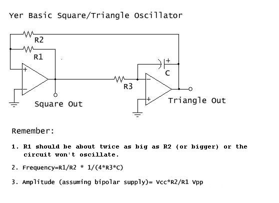
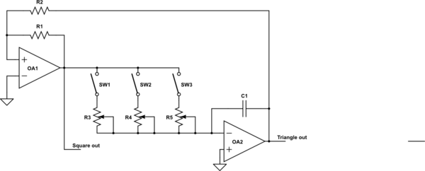
So, consider using an integrator and a schmitt trigger like this: -

enter image description here

Basically it relies on the integrator capacitor being charged and then discharged from the output of the schmitt trigger. Because it's an integrator you will have a very linear ramp-up and ramp-down due to the current in and out of the capacitor being set by the square wave amplitude and R3.

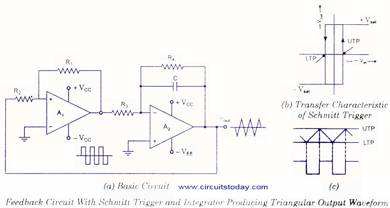
There are plenty of designs based on this type of circuit and here's another one: -

enter image description here

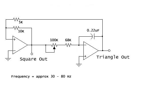
Here's the article that describes it in more detail. For tuning it you can turn R3 into a pot like the one below: -

enter image description here

Or you can use a pot in series with the positive feedback resistor on the schmitt trigger. You can even put the pot in place of R2.

There are variations of this circuit that allow pulse width modulation i.e. you can make the triangle wave more saw-like.


NEW SECTION about choice of op-amp.

The biggest problem area in this design is the comparator. Ideally you want it to switch its output from positive to negative in zero time but that won't happen. For instance the 741 is a bad choise because it has a large delay in dragging its output transistors out of saturation. This will likely be tens of microseconds added to the more normal propagation delay of about a micro second.

Then the 741 is slew rate limited on its output to 0.5 volts per micro second. If you have a +/-15V supply the typical output voltage levels will be at +/-14V (loaded with a 10k resistor). To change the output all the way from +14 volts to -14 volts takes 56 micro seconds and it needs to do this twice per oscillation cycle - that's 112 micro seconds. For most of the time while it's doing this, the integrator isn't really moving its triangle wave output but I reckon you could bank on at least 60 microseconds added to the oscillation cycle.

Also when you load the output the p-p voltage level drops - the data sheet says the 741 output level will drop from +/-14V with a 10k load to +/-13V with a 2k load.

So what does 60 us mean in this design? The op says that he halved the resistance and expected 800 Hz but only got 756 Hz. The time difference between one cycle of 800 Hz and one cycle of 756 Hz is 73 us i.e. probably everything can be put down to slew rate limiting.

To improve this get a much better op-amp circa 10V/us slew rate. Then run it from +/- 5V rails. A typical op-amp of this type might produce +/-4V output i.e. a delta of 8V and, due to the improvement in slew rate the "delay" would be about 0.8 us but what does this mean? Compare this to a 1Hz error in 800 Hz - this is a time delay per cycle of 1.6 us so now, using a 10V/us slew rate op-amp, gives a 1 Hz error at 1600 Hz.

To avoid the extra propagation delay (common to a lot of op-amps) when their outputs saturate, negative feedback can be used to limit the comparator output to maybe +/-2.5V. Use of series back-to-back precision shunt zeners may be able to do this but, as always, the devil is in the data sheet's details so I'm not going to propose anything hard and fast for this feature - I'd just look for an op-amp that is quick at coming out of saturation or go for a fast comparator with push-pull output.

\$\endgroup\$
10
  • \$\begingroup\$ Andy, I read his question as requiring a linear change in frequency with the pot. I don't think any of your examples satisfy this requirement. Do they? \$\endgroup\$
    – Transistor
    Commented Dec 19, 2015 at 11:45
  • \$\begingroup\$ @transistor here's what the op defines as linear: "It's also not linear. If I halve the resistance, the frequency is less than doubled". It appears to me that he wants that type of response i.e. if resistance halves then frequency doubles. \$\endgroup\$
    – Andy aka
    Commented Dec 19, 2015 at 12:22
  • \$\begingroup\$ That'll be a binary logarithmic response then. I asked him to clarify. \$\endgroup\$
    – Transistor
    Commented Dec 19, 2015 at 12:49
  • \$\begingroup\$ I tried to make the first circuit in your answer, with the Schmitt trigger and integrator. But I ran into the same behaviour where halving the resistance does not double the frequency. 2 parallel resistors tuned to 400Hz only give 756Hz combined, not 800Hz. \$\endgroup\$
    – Pepijn
    Commented Dec 20, 2015 at 15:06
  • \$\begingroup\$ what opamp did you use. It needs to be fast if you want accuracy. \$\endgroup\$
    – Andy aka
    Commented Dec 20, 2015 at 15:40
2
\$\begingroup\$

Your 555 oscillator will work much better if you use a CMOS version rather than the old bipolar version (and only load the output lightly). If you are hung up on 50.0% duty cycle, follow it up with a flip-flop (and regulate the supply voltage well because changes during the cycle will affect the duty cycle. That will work with any of the oscillator circuits.

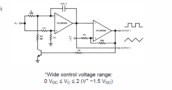
The below is a decent and very cheap single-supply VCO circuit from the LM324 datasheet:

enter image description here

You can use another of the four op-amps in the package as a voltage follower to buffer the input voltage from a pot. Replace the BJT with a MOSFET to get a bit more range at the low end, but the BJT is pretty good. The triangle wave has much less harmonic content than a square wave so it might be preferable for producing audio.

The above circuit produces a frequency that is linear with voltage, so with a B (linear) taper pot + buffer you will get a frequency that increases linearly with pot shaft rotation. Most of the other circuits have a period that increases linearly with pot rotation, so frequency is proportional to the reciprocal of the pot shaft angle of rotation.

\$\endgroup\$
1
\$\begingroup\$

If you build your oscillator to run at twice the desired frequency, and then put a flip-flop after it to divide by 2, the resulting wave will have a 50% duty cycle all the time.

\$\endgroup\$
1
  • \$\begingroup\$ That would still leave the problem that the 555 circuit isn't really k/RC, but has some non-linear response. Possibly due to the asymmetry in charging/discharging. \$\endgroup\$
    – Pepijn
    Commented Dec 19, 2015 at 10:09
1
\$\begingroup\$

Take your 555 circuit (or other frequency generator), and feed its output to a divide by 2 binary counter. All the counter IC's on the market are total overkill for a simple divide by 2, but they will still cost less than your potentiometer. The 4024 is one option (giving divide by 1,2,4,8,16,32,64,128, i.e 7 octaves of output) but there are many other options. http://www.nxp.com/documents/data_sheet/74HC4024.pdf

\$\endgroup\$
1
\$\begingroup\$

[Update after question clarified]

schematic

simulate this circuit – Schematic created using CircuitLab

A variation of Andy aka's feedback circuit with schmitt trigger.

When all switches are released the integrator will slowly drift to one of the supply voltages, depending on the offset and leakage current.

You'll have fun trying to tune this thing.


[Original answer]

Microchip have Application Note TB3071 provides a possible solution but it requires programming a chip.

In this technical brief, a PIC10F322 is being used to implement a simple voltage-controlled oscillator (VCO). Output frequencies range from 16 Hz to 500 kHz, with an internally generated clock source (no external crystal required). The VCO operates from a supply voltage of 2.3 to 5.5V, with current consumption of approximately 2.4 mA (5.0V V DD).

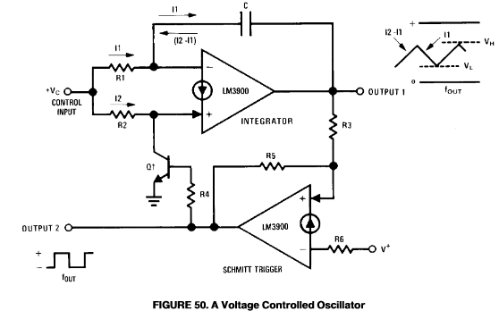
There's an interesting analog linear VCO on page 27 of TI LM3900 Current-Differencing Amplifiers. Frequency of output is linear with respect to Vin. It may do what you require.

enter image description here

\$\endgroup\$
4
  • \$\begingroup\$ The suggested integrator circuit also seems to have non-linear frequency behaviour, just like the 555 and relaxation oscillator. \$\endgroup\$
    – Pepijn
    Commented Dec 20, 2015 at 15:04
  • \$\begingroup\$ Why so? The resistors feed into a virtual earth so the integrating capacitor is fed with constant current. Halve the resistance between the squarewave and the non-inverting input and the charge rate doubles, doubling the output frequency. OA1 performs the schmitt trigger function at the same voltage levels so all should be well. \$\endgroup\$
    – Transistor
    Commented Dec 20, 2015 at 15:10
  • \$\begingroup\$ I don't know why so. But that is what I see when I build it. I tune two buttons to 400Hz, and when I press them both I get 756Hz, not 800Hz as expected. 200Hz+200Hz=392Hz. I'm puzzled. \$\endgroup\$
    – Pepijn
    Commented Dec 20, 2015 at 15:25
  • \$\begingroup\$ Reasons given in my answer. Op used a 741 and as a comparator will incur a delay of about 60us in changing state. This accounts for the error! A fast device is needed. \$\endgroup\$
    – Andy aka
    Commented Dec 20, 2015 at 20:16
1
\$\begingroup\$

You can't have frequency linearly proportional to RC, but you can have the period so controlled. Frequency is then k/RC.

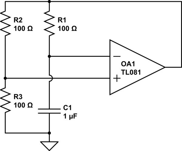
You could try a circuit based on this back of envelope sketch.

WARNING these component values will not make a sensible oscillator, though it may well simulate OK, they were merely the defaults when I created the schematic. You will have to figure out sensible values.

schematic

simulate this circuit – Schematic created using CircuitLab

This is a relaxation oscillator. Positive feedback is achieved via R2 and R3, with timing control via R1 and C1.

Note that this circuit as drawn requires dual rails, as C1 and R3 go to ground. It is straightforwrd to modify for single rail operation with an effective ground point.

The beauty of this circuit is that even if low values of R1 are loading the output of the amplifier such that its output drops, the drop applies both to the voltage on the timing resistor R1 and the hysteresis chain R2/R3, so the period remains unaffected by amplifier output impedance. The same goes for variations of the voltage rails.

This behaviour is in contrast to what would happen if you used a schmidt trigger inverter, like the 74HC14 for instance, in place of the amplifier+R2+R3 combination. It has an input hysteresis that is more or less constant, regardless of rail voltage and output drop, so these would affect the frequency.. You would not get 50% duty cycle either.

It is reasonable to have R2=R3, this doesn't provide a freq = 1/RC condition, but it's not far off. You can tweak the R2/R3 ratio to get exactly that formula if you want. Do it either analytically as an exercise, or play with values in a simulator. I'd tend to just throw a couple of 10k or 100k in those positions without further thought.

You will have to make sure that the hysteresis that you choose with R2 and R3 stays within the common mode input range of the amplifier. The default amplifier that comes up in the schematic is a TL081, which includes the +ve rail but not GND in its common mode range. There are many other amplifier choices which can include ground or both rails, but they are not necessary unless you want to use extreme R2/R3 ratios.

CAVEATS

This circuit is linear and 50% duty cycle to first order, that is, for when the op-amp is behaving ideally.

Real op-amps will have a finite slew rate and gain bandwidth product. Once the delay after switching becomes a significant part of the period, the frequency will fall back from the linear law it had at lower frequencies. Use a fast enough op-amp.

Although both the hysteresis and charging current are controlled by the same pin, the hysteresis value is only relevant at the moment of switching, whereas the charging current is valid for the whole period. If the output of the op-amp varies over the period, due to excess current being drawn by R1 and R2, or by excess output loading, or by non-infinite gain, the output frequency will fall short of the linear law at higher frequencies. Keep the minimum value of R1 sufficiently high.

If the resistors become too large, offset currents taken by the amplifier will become a significant fraction of the currents passing through the resistors, and will distort the duty cycle away from 50%.

There are better designs that have fewer defects, working in current rather than voltage mode for instance, if better linearity at high freqeuncies is needed.

\$\endgroup\$
10
  • \$\begingroup\$ Oh, looks promising. Will give it a go and accept if it works. I'll have to think a bit about the R2=R3 situation, and maybe solve some differential equations. This seems helpful en.wikipedia.org/wiki/… \$\endgroup\$
    – Pepijn
    Commented Dec 19, 2015 at 10:11
  • \$\begingroup\$ yes, that relaxation oscillator link is a good find, I don't think you need to go as far as differential equations! \$\endgroup\$
    – Neil_UK
    Commented Dec 19, 2015 at 13:59
  • \$\begingroup\$ So can you clarify the R2=R3 situation a bit? Is the goal to hit the center of the opamp voltage range? \$\endgroup\$
    – Pepijn
    Commented Dec 20, 2015 at 11:05
  • \$\begingroup\$ R2 and R3 set the hysteresis by their ratio, which sets the k value in the equation freq = k/RC, and must be chosen to keep the input voltage in the opamp CMR. If R3 = 0.1R*R2, then the frequency is high, and the input voltages only swing slightly either side of mid rail. If R3 = 10*R2, the input voltage gets very close to the rails and the frequency is low. R2 = R3 is perfectly reasonable, but doesn't give you k=1. As both hysteresis and R1 voltage depend on the same terminal voltage at the output, which should give 50% m/s, even for small errors of mid scale voltage. Check this please! \$\endgroup\$
    – Neil_UK
    Commented Dec 20, 2015 at 13:21
  • \$\begingroup\$ That would influence K, but no matter the value of K, if f=k/RC, then f/2=k/2rc. But his is not the case. If I tune the suggested circuit to 440Hz, I measure 1.32kOhm resistance. But 0.66kOhm produces only 829Hz instead of 880Hz. This is the puzzling part to me. I could not care less about k. \$\endgroup\$
    – Pepijn
    Commented Dec 20, 2015 at 13:38
0
\$\begingroup\$

For accurate linear control, you want to build an rc oscillator in a way that ensures the capacitor is not resistively loaded more than by any means necessary, so both comparators and output buffers should preferrably be FET input devices.

For an exact 50% duty cycle, the frequency divider already suggested is definitely the best solution.

If a good sawtooth shape is also desired, charge the capacitor from either a current source or from a voltage that is very high compared to the amplitude at the capacitor.

\$\endgroup\$
0
\$\begingroup\$

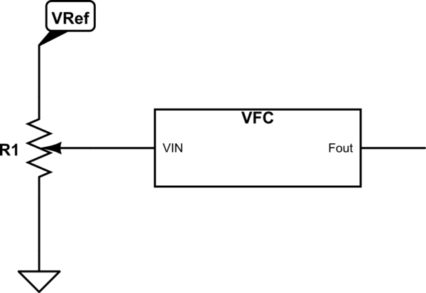
What you are asking for is called a Voltage to Frequency Converter (VFC). This can be used with a variable resistor configured as a potentiometer

schematic

simulate this circuit – Schematic created using CircuitLab Rather than mess around with timers, go with a real VFC, such as the Fairchild KA331 which is available from Digikey.com for less than a buck. Depending on how much support circuitry you want to provide, you can get VFC linearities of .01%, which is far better than the linearity of your pot.

And, as has been suggested, put a divide by two on the output to get exactly 50% duty cycle. As long as you want a square wave.

\$\endgroup\$
0
\$\begingroup\$

If you really want a square wave (50% duty cycle) output, then start with a arbitrary duty cycle oscillator and divide the output by two.

Now the problem is only making a oscillator with controllable frequency. That's easy with many candidate designs already out there. Here are a few possibilities:

  1. Set up a comparator with hysteresis, and feed it from a capacitor being charged up thru a resistor to a variable voltage. When the cap gets to the high threshold, the output triggers and hard discharges the cap to ground. The cap waveform will be a rounded sawtooth with slow rise time and fast fall time. The circuit outputs a pulse during the fall time. This goes into a flip-flop set up as divide-by-2, which produces the final output.

  2. Same as #1, except that the cap is being fed from a adjustable current source. This will allow for more linear control of the period, and the cap waveform will be a true sawtooth (the rising part will be linear, not a exponential decay as before).

  3. Same as #1 but instead the resistor to the fixed supply is adjusted. This changes the time constant and average slope of the rising part of the exponential "sawtooth".

There are many other circuit topologies to make a frequency-adjustable oscillator. They vary on what parameter is being adjusted, and how linearly or not that maps to period or frequency.

Again, the main trick here is to follow the oscillator with a 2x divider so that its native duty cycle can be whatever falls out conveniently.

\$\endgroup\$

Your Answer

By clicking “Post Your Answer”, you agree to our terms of service and acknowledge you have read our privacy policy.

Not the answer you're looking for? Browse other questions tagged or ask your own question.