2
\$\begingroup\$

Sample voltage divider circuit:

schematic

simulate this circuit – Schematic created using CircuitLab

In this circuit, \$Vout\$ is, by Ohm's Law: $$ Vin * \frac{R2}{R1+R2} $$

But this circuit, by itself is pretty much useless right? That is: If we don't connect \$Vout\$ to a load, then there is no reason to divide a voltage. So a better representation might be:
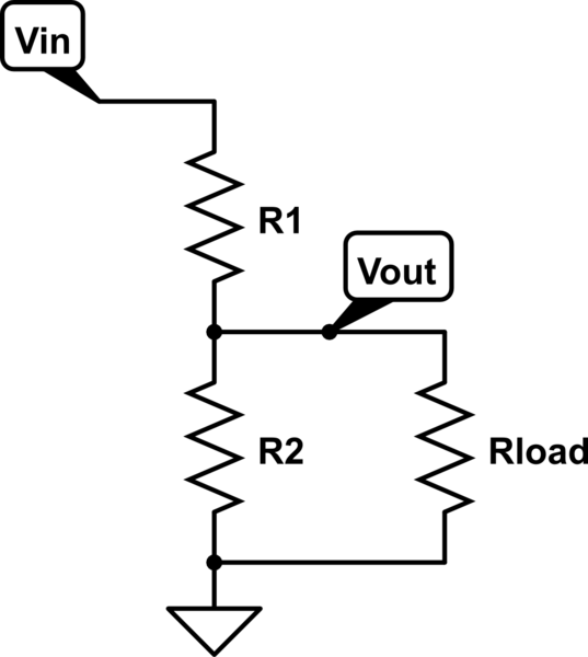
schematic

simulate this circuit

But in this circuit, \$Vout\$ is, by Ohm's Law:

$$ Vin * \frac{Rload*R2}{R1*R2+Rload*(R1+R2)} $$

So why isn't a voltage divider circuit formula stated as the second version, rather than the first one?

\$\endgroup\$
6
  • \$\begingroup\$ It is implicit that R2 is either open circuit (no load) or the load value has modified R2. \$\endgroup\$
    – Andy aka
    Commented Jan 21, 2016 at 8:52
  • 3
    \$\begingroup\$ Why assume the load is resistive, and connected to 0V? There are other options which produce other equations. \$\endgroup\$
    – Martin
    Commented Jan 21, 2016 at 8:52
  • \$\begingroup\$ @Martin You are right. But then, what is the point of providing any formula at all? Isn't stating that "Vout will depend on the nature of the load" more accurate? \$\endgroup\$
    – Utku
    Commented Jan 21, 2016 at 9:00
  • 2
    \$\begingroup\$ The formula is there to make the calculations. I use that formula very often. It only applies to this specific circuit but that is not a problem because in my circuits I will use it properly (Rload is very large). Your "Vout depends on the nature of the load" does not help me design anything, it does not provide me any useful information nor any way to design a voltage divider. \$\endgroup\$ Commented Jan 21, 2016 at 9:06
  • \$\begingroup\$ Search for something called "buffer" it is an op amp circuit that keep the output voltage the same. And it will not change after adding R load. There is another easy solution is to adjust R2 so that when you add R load, the equivalent resistance of them will make the correct ration of voltage divider equation. \$\endgroup\$ Commented Jan 21, 2016 at 9:10

2 Answers 2

5
\$\begingroup\$

"But this circuit, by itself is pretty much useless right?" No it isn't. Very often the Rload you introduced in your 2nd circuit has a very high value. An example would be the input of a CMOS opamp (Rin = 1 T ohm, that is 1000 Giga Ohms). In this case Rload can be ignored.

Also, I do not need your 2nd circuit and formula because when I know that Rload is significant I will first calculate the parallel resistance equivalent of Rload and R2 and then calculate the value of R1 (using the simple formula) from the required voltage division ratio.

Engineering is also about making the correct assumptions on what you can ignore so that the calculations you need to do remain as simple as possible. Simple calculations are less error prone. Simple calculations are easier do to in your head and maybe using a calculator. Personally I'm too lazy to use complex formulas (like the one for your 2nd circuit), I prefer simple ones.

\$\endgroup\$
3
  • 1
    \$\begingroup\$ "Also, I do not need your 2nd circuit and formula because when I know that Rload is significant I will first calculate the parallel resistance equivalent of Rload and R2 and then calculate the value of R1 (using the simple formula) from the required voltage division ratio." Yes. But the problem is, many resources do not state that this formula is just an approximation, and that it is not accurate in cases where Rload is not much bigger than R2. \$\endgroup\$
    – Utku
    Commented Jan 21, 2016 at 9:04
  • \$\begingroup\$ I have news for you: almost EVERY formula in electronics is an approximation ! The trick is to decide if the approximation is good enough. As an engineer you must realize that the voltage divider only works according to the formula when the Rload is large compared to value of R2". If that needs to be 10x as large or 100000x as large is up to you. If you want 0.0001 % accuracy then you will need a higher Rload than if you would be satisfied with a 1% accuracy. Most resistors are 1 % accurate so going for 0.0001 % accuracy is often pointless. \$\endgroup\$ Commented Jan 21, 2016 at 9:16
  • 4
    \$\begingroup\$ That formula is totally accurate for the circuit as drawn. If you want to use a different circuit, one with Rload in parallel to R2, then use the formula for the different circuit. \$\endgroup\$
    – Neil_UK
    Commented Jan 21, 2016 at 9:41
3
\$\begingroup\$

In most uses of a voltage divider Rload is very high compared to R2 so Rload does not introduce a significant error in Vout. Rload will often be the input to an op-amp, comparator, or ADC, which all have a very high input impedance.

You also have some degree of choice over the values of R1 and R2. If you want to produce a Vout of Vin/2 for use as a reference voltage for an op-amp then you may chose R1 and R2 to be 10k or even 47k. If you know that Rload is not quite so high (say the reference voltage for a DDR3 memory IC) then you may chose R1 and R2 to be 1k.

In case where Rload is low then most engineers would use high values of R1 and R2 (say 47k) and feed this through a non-inverting buffer so that Rload does not affect Vout.

One of the problems of trying to take Rload into account in the equation is that usually you do not know the precise value of Rload, or it can change dynamically.

\$\endgroup\$

Your Answer

By clicking “Post Your Answer”, you agree to our terms of service and acknowledge you have read our privacy policy.

Not the answer you're looking for? Browse other questions tagged or ask your own question.