0
\$\begingroup\$

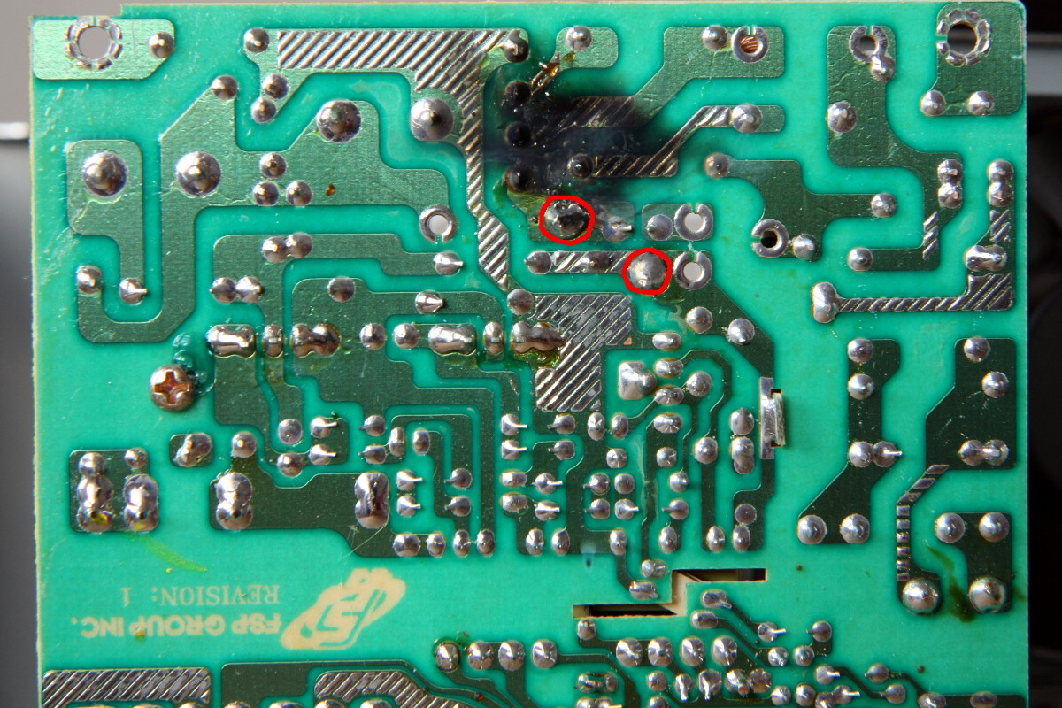
I was probing around an old ATX PSU to inspect voltage levels in the primary section. The first 15 minutes went smooth (bridge rectifier inputs, big caps, Power IC Vcc, etc..) but as soon as I probed the solder pads of the large coil circled in red in the picture, a short happened with the usual bang, sparks and smoke.

ATX PSU

First question: what is that large coil (Hi-Pot) connected to the primary side? Is it part of the EMI reduction circuit?

Second (probably stupid) question: my DMM has 10Mohm input impedance when used as voltmeter. How can I cause a short like that if I am careful to ensure that meter probes do not touch one another and that I do not short any PCB tracks with the probe tip?

Probed solder pads

I am extremely careful when I work on energised circuits, so I am rather annoyed by what happened as I may make the same mistake again if I do not understand exactly what I did wrong.

A last question related to general safety: is there any difference between using a 1:1 (230VAC -> 230VAC) isolation transformer vs connecting the appliance to be probed directly into the mains using a lead without the earth wire (or with such earth pin isolated/disconnected)?

Thanks to the community for your precious help.

\$\endgroup\$
20
  • 6
    \$\begingroup\$ You ask questions about an ATX power supply. You poke around in it while it is LIVE. Then it goes BANG and you're surprised ???? Geez ! If you need to ask questions about a power supply you should not even be poking around in it let alone a LIVE one. First educate yourself then so you would learn why not to open them. And yes of course you made a short, you were obviously not careful enough despite what you write. \$\endgroup\$ Commented Feb 2, 2016 at 11:12
  • 4
    \$\begingroup\$ @FakeMoustache, telling someone not to try to fix a piece of equipment is not a useful response and just contributes to the "just leave it to the experts" mentality of ignorance and helplessness. Your comment, "...a power supply you should not even be poking around in..." is rude and patronizing. I would encourage the OP to pay no attention to you. \$\endgroup\$
    – user98732
    Commented Feb 2, 2016 at 11:34
  • 4
    \$\begingroup\$ @Entropivore then you are going to have to say the same to me. No schematic, no understanding, no recognition of what certain components do = nothing to be gained by poking around. This type of poking around may have been useful in the early days of vivisection but there was little risk of electrocution. \$\endgroup\$
    – Andy aka
    Commented Feb 2, 2016 at 11:56
  • 3
    \$\begingroup\$ Courage is handy for getting dead, especially when fortified by ignorance and blended with high voltage. Recognizing when you are a user or not (in the "no user servicable parts inside" sense) is one of those things that helps to keep you alive - or not. \$\endgroup\$
    – Ecnerwal
    Commented Feb 2, 2016 at 12:25
  • 2
    \$\begingroup\$ Is your meter still working? Was it on ACV or DCV on a suitably high range. What was its certified working voltage? I assume you are using 110 VAC mains as large cap is labelled 200V 470 uF. IF meter broke down it can cause short and excitement but this would usually be obvious afterwards. If meter was not on HV Volts or if eg positive lead was in 10A socket "things can happen". No obvious action NOT caused by a fault condition applied by you seems likely. \$\endgroup\$
    – Russell McMahon
    Commented Feb 2, 2016 at 13:25

4 Answers 4

2
\$\begingroup\$

I'm not sure what the big inductor is for. It doesn't look like part of an EMI filter to me, since that would typically be a common mode choke with four leads, and this apparently has only two. (That's probably a common mode choke on the circuit board next to the the torroidal inductor, labeled FL3, with the white bobbin and the ferrite core.) It's also rather large for that. My guess (and it's only that) is that it may be part of a power factor correction circuit. BTW, "HI POT" is short for "high potential", and generally just means that it has passed an insulation breakdown test.

I don't have any really great theories about the short, except to say that, especially if you're running on 230VAC mains, the peak voltages in such circuits can be quite high, especially in circuits with big inductors. So it's possible that you didn't even make true metal-to-metal contact but simply decreased the air gap just enough to cause an arc.

Re the isolation transformer, YES, there is a difference! Please use the isolation transformer! Disconnecting the safety ground lead on the equipment under test doesn't remove the potential between the hot circuit and earth ground, so you are still exposed to danger. Even with a well-insulated, floating DMM, you can still have an accident. Sometimes engineers will float the ground on oscilloscopes so that they can probe line-side circuits, but this is still dangerous. An isolation transformer is the only reasonably safe way to work on these things.

\$\endgroup\$
5
  • 1
    \$\begingroup\$ Thanks for your answer. Let's suppose I had connected the ATX PSU to an isolation transformer. Am I right to say that it would not have protected the PSU from the over-current inrush? Its only aim is to float the equipment under test to prevent electrocution in case I came in contact with a live conductor (which did not happen). And talking about safety, am I right to say that an RCD only (with no isolation transformer) wouldn't have helped (tripped) either if the over-current fault did not cause a current leakage to ground? \$\endgroup\$
    – Amanda
    Commented Feb 2, 2016 at 15:48
  • \$\begingroup\$ I do understand what you write about the scope ground and I agree. I think it's dangerous to float a scope. A much safer approach is to make differential measurements. On the other hand, I still do not understand how an isolation transformer is any different from the earth-less lead I mentioned. You write: "Disconnecting the safety ground lead on the equipment under test doesn't remove the potential between the hot circuit and earth ground", but isn't this what happens with an isolation transformer? A fault to chassis will not be cleared as the earth connection is missing, in both scenarios. \$\endgroup\$
    – Amanda
    Commented Feb 2, 2016 at 15:51
  • 1
    \$\begingroup\$ @Amanda Think of things this way: The mains voltage is usually earth-referenced on the remote side. So if you connect the live wire to something else at your side that is grounded by a means other than the main ground installation, the current would still flow to the point where the remote side is grounded. On the other hand, if you connect an isolation transformer and use it,then current going out of the transformer needs to go back in to complete the circuit. \$\endgroup\$
    – AndrejaKo
    Commented Feb 2, 2016 at 19:30
  • 1
    \$\begingroup\$ Thanks for your clarification. I think I got it. Both scenarios will make the appliance-under-test float, but only the isolation transformer can ensure a physical break in the live electric conductor (via magnetic inductance) that will prevent completion of the circuit and therefore electrocution. \$\endgroup\$
    – Amanda
    Commented Feb 2, 2016 at 22:27
  • 1
    \$\begingroup\$ I can't emphasise strongly enough that neither an RCD nor an isolation transformer will prevent the possibility of a lethal shock from this sort of circuit, because of the presence of capacitors charged to high DC voltages. \$\endgroup\$
    – nekomatic
    Commented Feb 3, 2016 at 9:52
2
\$\begingroup\$

Amanda, and welcome to the site.

Assuming your power supply looks something like this, your coil is the primary input inductor, shown at upper left in the schematic.

Now, what happened? Having been in similar situations a few times, I'd guess that you got distracted. You were holding both probes to the board, looked away at your meter, and BANG!. When you twisted your head your body followed, your grip on the probes shifted and you did, in fact, short out the probes. This put something like line voltage across your poor little coil, and it went to that Great Junkyard In The Sky. Very sad. Of course, that sort of excitement is (deep down) what draws a lot of us to messing around with electronics.

Please excuse FakeMoustache's response. He was just a bit appalled that you're putting yourself at risk by poking around in mains-connected circuitry without knowing much about what you're doing, and he's right - it's dangerous. You can take various precautions, but sooner or later you'll get something dramatic happening. Actually, you got off lightly. Very early in my career I lost a perfectly good pair of wire cutters when I tried to cut a live power cable. No shock involved, but the cutter edges were toast.

\$\endgroup\$
1
  • 1
    \$\begingroup\$ Thanks. Unfortunately your guess is wrong. As I wrote in my initial post, I did not short the probes at all. No distractions either, as I kept my eyes well focused on what I was doing, being aware of the danger. The bang happened the very moment the tip of the red probe touched the second pad in the image. I posted my questions because I feel I did not make any obvious mistake. I generally do not like wasting people's time with questions that can be answered by a DuckDuckGo search. \$\endgroup\$
    – Amanda
    Commented Feb 2, 2016 at 17:34
1
\$\begingroup\$

There is a reasonably-good chance that in fact, your meter's internal insulation failed and arced-over internally.

I honestly don't know what that off-board inductor is used for but my guess is that it's part of the Power Factor Correction circuit. If so, it's probably part of a boost supply that generates a nominal 400 Vdc. But that's only a Wild-Assed-Guess (WAG).

Regardless, many inexpensive DMMs are NOT constructed as they should be and do not have adequate clearance and creepage distances internally. They may work properly to their rated voltage but they simply can't withstand any sort of transient spikes.

Interestingly enough, old-school analog meters ARE properly constructed internally and will often withstand many times their rated voltage without suffering insulation failure. I'm talking about the old Simpson 260 or Avo meters from years gone by.

Part of that construction is because those meters were used to troubleshoot tube-type equipment with plate voltages of 250 to 450 Vdc or higher. It was not uncommon to see plate voltages well in excess of 1KV in transmitters.

Add to that the peak voltage swing that occurs with AM modulation - that 1KV plate supply swings up to almost 2KV peak.

Those old meters could (and did) withstand those voltage levels with no problems.

Modern DMMs made by reputable manufacturers such as Fluke are built to deal with those kinds of voltage levels. However, many of the inexpensive DMMs that come out of Asian factories are not. There are documented cases readily found with Internet searches of injuries caused by those inexpensive meters being used on 480 Vac power systems.

\$\endgroup\$
0
\$\begingroup\$

Please see Benchtop circuit breaker where I address some of the questions you raise concerning isolating transformer.

schematic

simulate this circuit – Schematic created using CircuitLab

Figure 1. Benchtop mains power supply - modified for 230 / 115 V operation.

For working on switched-mode PSUs risk can be reduced by using a centre-tapped transformer to give 115 V where the PSU is so rated.

A last question related to general safety: is there any difference between using a 1:1 (230VAC -> 230VAC) isolation transformer vs connecting the appliance to be probed directly into the mains using a lead without the earth wire (or with such earth pin isolated/disconnected)?

The danger with disconnecting the earth wire is that the case and heatsinks may go live due to poor insulation somewhere. Since these present much larger areas and 3D shapes they may be touched accidentally. Another concern may be that the secondary is earth-referenced and that may go live-ish too.

\$\endgroup\$

Not the answer you're looking for? Browse other questions tagged or ask your own question.