4
\$\begingroup\$

Background

I wish to power my circuit with a Lithium-ion battery LIR2032 (around 40 mAh capacity). These batteries have a voltage that goes from 4.2V to 3V typically during their discharge cycle.

My circuit (running at 3.3V) has a maximum current requirement of around 20mA -- although I should state that this is only the peak draw occurring in less than 0.1% of the time; the circuit draws below 1uA the remaining 99.9% of the time. It will be a sensor node which every 30s wakes up and emits data using nRF24.

Question

What would be the best way to efficiently convert the (changing) output voltage of a Lithium-ion battery to less than 3.6V which is required for the MCU?

Efficiency is very important here, because of very limited capacity of the battery. Also I have no problem with varying voltage because the circuit can work with 3.0 or less, so it does not have to be precise 3.3V or similar, just need to be below 3.6 at all times.

EDIT: I come to an idea, I can find MCU which is capable up to 5.5V (so it can work directly from battery). So only for nRF24 module lower voltage is required. Please look at schematic. What do you think? The idea here is to turn on transistor only when required (transmitting). And even base current is used so only losses are in transistor (for voltage dividing).
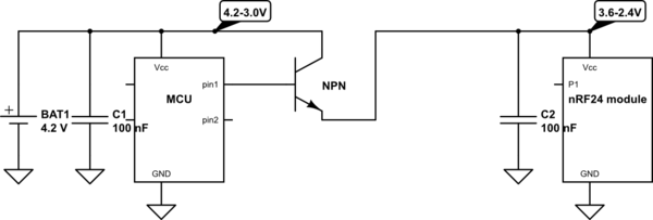
schematic

simulate this circuit – Schematic created using CircuitLab

\$\endgroup\$
8
  • 1
    \$\begingroup\$ First of all, 2032 are not lithium ion button cells, and their voltage drops quite quickly to the nominal 3V and also their internal resistance is quite high with ranging from 10-50Ω with designed loads of 15kΩ and draw of 200µA \$\endgroup\$
    – PlasmaHH
    Commented Feb 22, 2016 at 11:22
  • 4
    \$\begingroup\$ You are talking of CR2032. I plan to use LIR2032 which are Lithium-ion batteries. The reason I am trying to do with LIR2032 is because I plan to add some small solar cell to be able to top-up the battery. \$\endgroup\$
    – Darko
    Commented Feb 22, 2016 at 11:29
  • 1
    \$\begingroup\$ whoopsie, right. \$\endgroup\$
    – PlasmaHH
    Commented Feb 22, 2016 at 11:30
  • \$\begingroup\$ :) If I fail to find good way to convert voltage down using LIR2032, I may switch to CR2032. Regarding internal resistance I was hopping that ceramic capacitor of 1uF would be able to handle "high surges" when circuit is transmitting. \$\endgroup\$
    – Darko
    Commented Feb 22, 2016 at 11:35
  • 3
    \$\begingroup\$ Be careful with just slapping on high amounts of capacitance, due to leakage you might increase your overall current consumption. I think your regulation question however might already have an answer here: electronics.stackexchange.com/questions/38782 if it doesn't maybe edit into your question on why it isn't sufficient, my pure guess would be that your efficiency requirements are not met, which would be nice to be expressed in numbers \$\endgroup\$
    – PlasmaHH
    Commented Feb 22, 2016 at 11:40

4 Answers 4

7
\$\begingroup\$

Under most circumstances, efficiency might imply a switchmode regulator, but the lowest quiescent current available is about 3µA or so, as with this regulator.

As that is quite a deal more than your circuit uses for most of its life, an ultralow Iq linear LDO regulator may be better suited to this application as current from the battery is the key here for long life.

The lowest Iq regulator I have found (I have some products in an energy harvesting application) is the TPS783, with a headline 500nA quiescent current.

There are other options, such as the NCP4681 with 1µA quiescent current.

I am sure there are others out there, but 500nA for a regulator is extremely impressive.

If you set V(reg) to 3V (the nominal minimum for most 3.3V devices), then you should have a battery useable to <3.2V

As you intend to use some solar energy, an Energy harvesting solution might be the way to go.

\$\endgroup\$
3
  • \$\begingroup\$ 500nA looks promising. Not as efficient as hopped but acceptable. I was hopping to find some charge circuit or similar which could be more efficient, but it is questionable if something like that exists. \$\endgroup\$
    – Darko
    Commented Feb 22, 2016 at 12:06
  • 1
    \$\begingroup\$ 500 nA quiescent for any regulator is, quite honestly, astounding. \$\endgroup\$ Commented Feb 22, 2016 at 18:09
  • \$\begingroup\$ @Darko look at my answer, the Iq and efficiency wasted by the regulator is dwarfed by the power saved by regulating down. \$\endgroup\$
    – Passerby
    Commented Feb 22, 2016 at 19:01
3
\$\begingroup\$

You might be able to get away without any voltage regulation at all.

I'm successfully running an Atmel ATmega328 with a nRF24L01+ transceiver straight of a 2032 cell. The mega328 and nRF24 don't really seem to care about the voltage.

What was really important in my setup were the decoupling caps directly on the nRF24L01+ module. As soon as I soldered 100n ceramic caps onto the VCC and GND pins of my RF transceivers, everything worked fine.

Also: with many MCUs this setup allows you to measure your own battery voltage which (for a remote sensor node) might be very nice to have.

\$\endgroup\$
6
  • 1
    \$\begingroup\$ When you say 2032 cell, you probably mean CR2032 which does not go above 3.6V. LIR2032 goes up to 4.2V which (at least officially) nRF24L01+ could not handle. ATmega328 could work up to 5.5V so it should be fine. \$\endgroup\$
    – Darko
    Commented Feb 22, 2016 at 12:58
  • \$\begingroup\$ I have even used an lithium-ion 18650 cell (4.2v max.), without any problems as well. It works quite well for me. \$\endgroup\$
    – Manawyrm
    Commented Feb 22, 2016 at 13:00
  • 1
    \$\begingroup\$ That is interesting. I guess that lot of chips could handle little above spec (In this case ~17% above). But I am not sure this is good practice, because you do not have guaranties that it will work fine after some time (degradation) or at all (I guess some parts would even fail on first try). \$\endgroup\$
    – Darko
    Commented Feb 22, 2016 at 13:06
  • 2
    \$\begingroup\$ The question here is, whether you are doing this as a personal project or as part of a professional electronics design. \$\endgroup\$
    – Manawyrm
    Commented Feb 22, 2016 at 14:13
  • 1
    \$\begingroup\$ Good point for personal use. One could try and see does it work in his case. \$\endgroup\$
    – Darko
    Commented Feb 22, 2016 at 14:48
2
\$\begingroup\$

Just recently read an app note that targets your same circumstances. Using power solutions to extend battery life in MSP430 applications By TI's Michael Day. While it uses the MSP430 as its target, the same applies to any MCU.

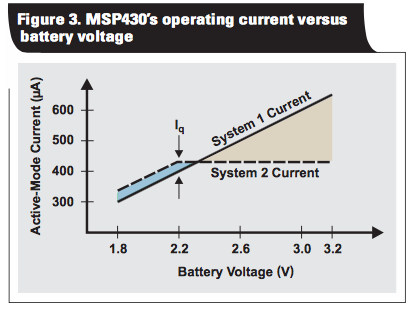
Depending on the MCU's Current vs Voltage, and Voltage vs Clock Speed, using a low Iq LDO will be much better than powering the MCU directly off the battery. The example uses 2x AA, and a TPS780xx regulator with 0.5µA IQ, at 90% efficiency. The active mode current difference is ~175µA.

enter image description here

The lower the clock speed and input voltage, the lower the current used is.

In this second example, System 1, with the MSP430 powered directly from the batteries, operated for 223 hours before shutting down. System 2, which used a TPS780xx to drop the MSP430 operating voltage to 2.2 V, operated for 298 hours before shutting down. The addition of the TPS780xx LDO, which operates at 90% efficiency with these operating conditions, extended battery life by 30%.

Later on, it even compares the Low Power Mode/Sleep currents:

In low-power mode 3 (LPM3), the MSP430FG4618’s operating currents at inputs of 3.3 V and 2.2 V are 2.13 μA and 1.3 μA, respectively. With the TPS780xx’s 0.5-μA quiescent current added, the battery currents are 2.63 μA and 1.8 μA, respectively. DVS reduces battery current by 26% under these conditions. This reduction of LPM3 battery current is critical for systems that spend a significant amount of time in sleep mode.

While specifics are important, using a low Iq LDO, and targeting the lowest voltage your MCU and the radio can use, you'll cut down on the current required compared to straight off the battery.

\$\endgroup\$
1
  • 1
    \$\begingroup\$ Great article. :) \$\endgroup\$
    – Darko
    Commented Feb 22, 2016 at 22:34
1
\$\begingroup\$

You want to use LIR2032 because you want to charge it from a solar cell. The easiest solution would be just not to charge it over 3.6V. Place a zener diode across the battery. Internal resistance of a small solar cell should be enough to limit the current flowing through the zener diode.

\$\endgroup\$
1
  • \$\begingroup\$ This is possible, but that way I would be using only small part of capacity... Thanks for answer. \$\endgroup\$
    – Darko
    Commented Feb 22, 2016 at 22:37

Your Answer

By clicking “Post Your Answer”, you agree to our terms of service and acknowledge you have read our privacy policy.

Not the answer you're looking for? Browse other questions tagged or ask your own question.