1
\$\begingroup\$

I have a challenge to push 500 Watts (15V) at 100 meters of telco telephone cable (0.088mm2, 28 AWG, 200Ohm/km, 500MOhm insulation).

The only way to achieve this is by boosting the voltage up to nearly 1kV and then - back to 15V.

The problem is that on the sinking side I have a very limited space (flat-hand barely fits), so cannot use any transformers.

Several sources on SMPS design seem to propose isolated topologies (is this for safety reasons?).

SMPS topology can be chosen from any type (yet, I'd prefer simplicity):

  1. Boost or Buck
  2. DCM Flyback
  3. Forward Push-Pull
  4. Half-Bridge
  5. Resonant LLC

looking to this source, however, 1-3 is recommend for sub 150 Watt range. The rest are ok for 500 Watts, but all contain transformers which I cannot fit into the BUCK (not sure it that is a correct term to identify voltage down-conversion).

Ripple or EMI specs are of least importance (brushless motor will be powered). Conversion efficiency, however, does matter.

I'd feed a rectified and smoothed AC input into the boost converter. I'd replace diodes with kV MOSFETS and would likely introduce synchronous functionality. Inductor would probably require a careful winding to consider spark gap for the given voltages.

Could you please comment if this is a very bad choice?

By considering the constraints, what alternatives do I have on the BUCK-side then?

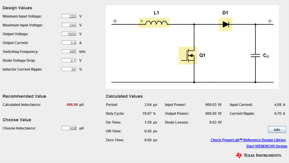
SMPS BOOST

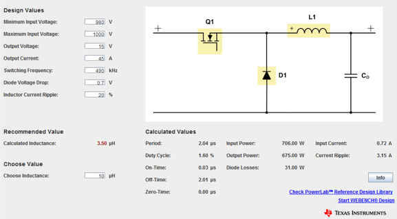
And I'd simply convert it down, most likely in synchronized fashion too. SMPS BUCK
\$\endgroup\$
6
  • 11
    \$\begingroup\$ You need to check the maximum voltage rating of the telco cable you intend to use. Standard (indoors) telco cable is only around 100V. \$\endgroup\$
    – Steve G
    Commented Feb 24, 2016 at 13:55
  • 5
    \$\begingroup\$ I would say the whole thing is a bad choice, besides the mentioned likely unsufficient rating of the cable you are creating quite some hazard there by running voltages onto cables where nobody would ever expect them to be. \$\endgroup\$
    – PlasmaHH
    Commented Feb 24, 2016 at 14:23
  • 1
    \$\begingroup\$ As Steve says, 1000v way exceeds the rating of telco cable, even if you have tested a bit on the bench (I have used mains flex for 10kV, and put 350v across enamelled copper wires, but neither of those are rated for that either). One defect in the insulation and you will have a problem. Run more current and allow yourself more voltage drop, or run a new cable. \$\endgroup\$
    – Neil_UK
    Commented Feb 24, 2016 at 14:27
  • 1
    \$\begingroup\$ For minimum space I would suggest forward mode with a transformer. If you use and inductor in buck configuration you have 2 problems. 1: the inductor has to have relatively high energy storage, so size is larger. 2: you will have a very low duty ratio for the switch, so you will need a very short on time which will be difficult to achieve with very high efficiency. \$\endgroup\$ Commented Feb 24, 2016 at 15:43
  • 2
    \$\begingroup\$ If you cannot fit a forward mode transformer, I don't think you will be able to fit a suitable inductor for transformerless operation. Also, it is on the low voltage side that you will need synchronous rectifiers. \$\endgroup\$ Commented Feb 24, 2016 at 15:55

4 Answers 4

2
\$\begingroup\$

Switched mode power supplies do not always use isolated topologies just for safety. Even when isolation is not required a tranformer-based design might be attractive since transformers are very convenient components for power supplies, especially when high power levels are involved.

Your assumption that transformers must be bulky heavy things is not entirely correct. Mains transformers are, because the frequency is so low that large amounts of steel are needed for preventing saturation at reasonable power levels. Transformers operating at 10 kHz or more are not necessarily bigger than inductors required for handling similar power levels.

A 1 kV buck or boost converter is not practical, as the switching transistors would have to conduct at least 42 A when on and block 1 kV when off. Applicable converter topologies would be the forward converter, the push-pull converter, and the full bridge converter, all being transformer based. Designing a 12 V DC to 1 kV DC converter is relatively straightforward, but the opposite is going to be a much bigger headache as you would need transistors able to block 1 kV + any transients, not to mention that you would have to find suitable input filter capacitors, design gate drivers, consider safety etc.

Finally you cannot reliably use small signal cables for carrying 1 kV. The isolation might be fine from milliseconds to days but it will eventually break down and short out.

\$\endgroup\$
0
\$\begingroup\$

Buck regulator also have an inductor which can get really big, so if you need some voltage stepdown technique that dont use any kind on magnetics, in this order of power, not possible.

about the size of the converter to get an idea look at a laptop charger, you can't really get more compact than them easily, the big ones have output powers around 120-150W. you need 500W also with higher voltage so thing become worse. so dimension wise it is also not possible.

so either get more room or more copper!

\$\endgroup\$
1
  • 2
    \$\begingroup\$ Yes, i've been studying on inductor types. Planar-ones (en.m.wikipedia.org/wiki/Magnetic_core) are used in i.e delta electronics server smps to reduce volume (see 400 Watt Q48SG). It seems, however, planar transformers do exist ads well... \$\endgroup\$ Commented Feb 24, 2016 at 21:33
0
\$\begingroup\$

Aside from the electrical problems that jms pointed out, there's also the issue of control. Converting 1000V to 12V means a PWM duty cycle of 1.2%. There's not much room to change the duty cycle in response to line or load transients. The narrow pulse width would probably complicate the electrical problems as well.

Your wiring is simply not suitable for this task. Looking at this page, your 0.08mm^2 wire (~0.32mm diameter) is limited to about 226mA. At 1kV, that gives you 226 watts, which is half what you need.

\$\endgroup\$
2
  • \$\begingroup\$ I'm not sure I understand this current limitation, Adam. Voltage drop calculation seems not to exceed -5% @ 1kV@1A and vice-versa - the max. current should probably limited by the tolerable voltage drop. I.e. dv=100V (900V on the output), resistance=40 Ohm (@200m), max. current = 2.5A \$\endgroup\$ Commented Feb 25, 2016 at 8:00
  • \$\begingroup\$ The power dissipation in the wires also matters. If the wires get too hot, it can melt the insulation. It's up to you whether you want to take the risk. \$\endgroup\$
    – Adam Haun
    Commented Feb 25, 2016 at 21:11
0
\$\begingroup\$

I have a challenge to push 500 Watts (15V) at 100 meters of telco telephone cable (0.088mm2, 28 AWG, 200Ohm/km, 500MOhm insulation).

I claim that you don't. Whatever solution you can come up with will cost more in your time alone than running a new cable that can do the job. I'm serious. Look at labor prices in Poland. Having someone dig a trench and run a new cable, or pull a new cable through the underground conduits, will cost less than you spending time to even think about it, I'm pretty sure :)

The cable you mention is not rated for 1000V between conductors. So that's where that line of thought ends. Nothing more to add here.

Given suitable cable, you don't need to do anything: push isolated (floating from Earth) 220V down the cable, and use whatever power supply you want on the other end. Done. The 500W isolation transformer will cost less than designing something that would cost less only when done in volume (your time isn't free).

If you really wanted to make the isolation system smaller, you'd be looking at an off-the-shelf 600W PFC module that produces 300VDC, then chopping that into a primary of a 1:1 isolation transformer - could be quite small, and I'd make the primary into a resonant tank to do zero-voltage switching. Then run the rectified output down the cable, and use it to power any off-the-shelf switching 12V power supply - they run off DC just fine. If you have access to aerospace junk, a 400Hz 1:1 500VA isolation transformer is much smaller than a 50Hz one, and you could run the 400Hz AC down the cable, and again feed it directly into an off-the-shelf supply - even though it's not written on the box, they run just fine off 400Hz instead of 50/60.

Why isolation? Extra precaution in case the cable was going where AC is either not normally expected, or where the cable may be subject to some inadvertent abuse.

\$\endgroup\$

Your Answer

By clicking “Post Your Answer”, you agree to our terms of service and acknowledge you have read our privacy policy.

Not the answer you're looking for? Browse other questions tagged or ask your own question.