0
\$\begingroup\$

I'm making a camera board using IMX225LQR image sensor. For this sensor you need 3.3V analog power supply and 1.8V, 1.2V digital power supplies. Also, the 1.8V power pins are close to the 3.3V analog pins. Thus I'd like to use ferrite bead to prevent noises in 3.3v rail generated by 1.8V digital power rails. But I have no idea what kinds of ferrite beads would be appropriate for this.

  1. DC resistance : Should it be as small as possible?
  2. impedance at each frequency: Should I look at impedances at 1Mhz, or 100Mz?

I'm going to use TPS62243 as 1.8V power supply. It's a switching regulator and has 2.25Mhz switching frequency. I wonder how you predict noise frequency, or if the 100Mz is general for noises in power rails.

\$\endgroup\$
3
  • \$\begingroup\$ Thank you for the link. But I couldn't find answer there. The example regulator written there has much smaller switching frequency. But I wonder if the noise from the TPS62243 would be significant around 100Mz so that I need the bead, for example, having 100 ohm impedance at 100Mz. \$\endgroup\$
    – SD11
    Commented Mar 9, 2016 at 9:54
  • \$\begingroup\$ @RogerRowland Would you please explain how the answer could solve my problem? Then, I'd like to remove my question. \$\endgroup\$
    – SD11
    Commented Mar 9, 2016 at 10:25
  • \$\begingroup\$ Well, I flagged it as a possible duplicate. If you agree it's a duplicate, then that's fine. If you don't agree it's a duplicate, you should maybe edit your question explain why it doesn't answer it and ask for some particular point to be clarified. Only you can decide if you have an answer or not. \$\endgroup\$ Commented Mar 9, 2016 at 10:37

1 Answer 1

8
\$\begingroup\$

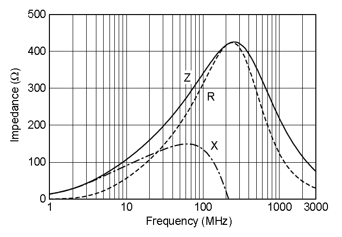
Ferrite beads tend to work effectively in the resistive region of their frequency response. Take a look at this: -

enter image description here

Sub 1 MHz to about 10 MHz the bead is acting as an inductor so, if you plan to use a bead as a filter then you need to have a capacitor to ground on the output side (quiet side) to form a low pass filter BUT beware, if you form a resonant low pass filter with a Q factor that is too high you can get severe ringing on the output (due to fast edges on the input noisy side) and destroy chips on the quiet side. Been there etc..

Between about 10 MHz and 300 MHz the inductance drops off rapidly (due to the ferrite material properties) and the bead looks resistive - broadly speaking, this is the target area that is best suited to ferrite beads because they really do dissipate the energy contained in noise that would otherwise have plagued your quiet circuitry. You still need an output capacitor in most cases though.

Above 300 MHz the bead is starting to act as a capacitor and progressively becomes useless.

How to select appropriate ferrite beads for power supply rails

Decide on what interfering frequencies you generally have. Decide on which of these interfering frequencies will give you problems. Choose the most appropriate bead or other method.

\$\endgroup\$
2
  • \$\begingroup\$ I had thought that the ferrite bead forms some sort of LC filter so we choose the cutoff frequency, the capacitor value and then the bead inductance. But it seems that this is not how we decide the ferrite bead specification. \$\endgroup\$
    – quantum231
    Commented Jul 6, 2023 at 17:19
  • \$\begingroup\$ It does form a parallel resonant circuit but a lossy one; i.e. one that doesn't have infinite impedance (resistive) but, instead, one that is tens of ohms to hundreds of ohms resistive. That resistance burns up the unwanted energies of noise and spikes @quantum231 \$\endgroup\$
    – Andy aka
    Commented Jul 6, 2023 at 17:30

Not the answer you're looking for? Browse other questions tagged or ask your own question.