3
\$\begingroup\$

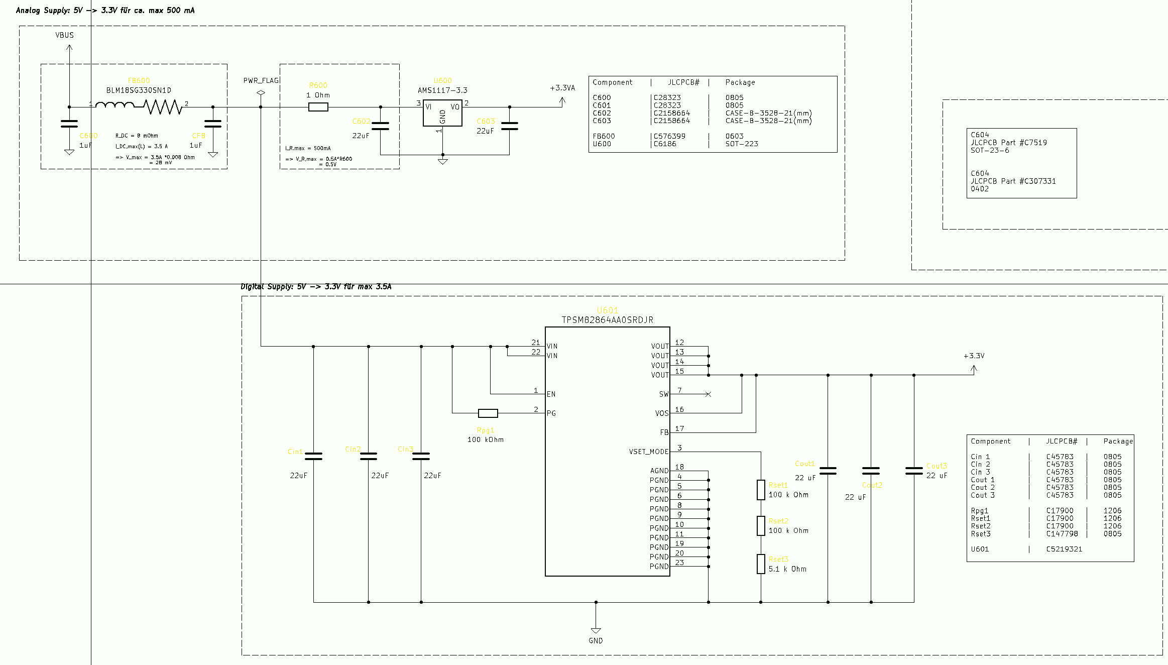
I am creating a mixed signal PCB which has two separate supplies: A buck converter for the digital section and an LDO Regulator for the analog one.

Each regulator steps down 5 V from a USB-C supply to 3.3 V. 
The digital section draws up to 3A, while the analog section draws up to 500 mA.

For the digital side, I am using a TPSM82864AA0SRDJR Buck Converter (lower regulator on the picture, 2.4 MHz switching frequency) and for the analog section, an AMS1117-3.3V, both powered by the VBUS supply line (USB-C, see schematic on the top left).

I have placed a Pi filter consisting of two 1 µF capacitors and a ferrite bead (capable of handling the needed current) in order to suppress the high-frequency noise from the (usually very noisy) USB-C supply rail before reaching my voltage regulators.

I want to ask if this Pi filter arrangement is a good idea considered my regulator setup, or if a different approach would be more appropriate.

Thank you very much in advance.
Greetings,
 Leandro.

enter image description here

enter image description here

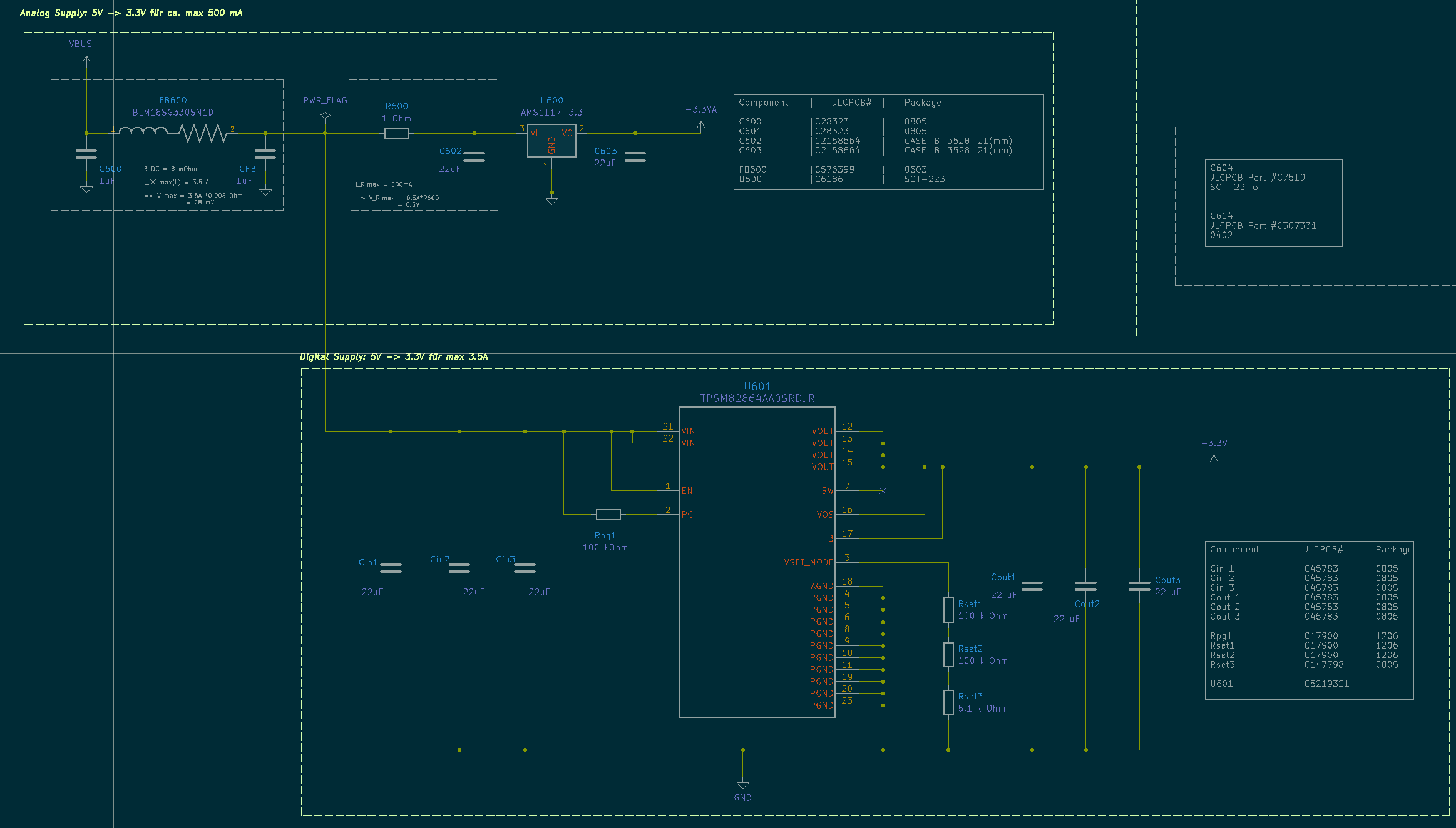
Something like this is far more readable. It's not perfect - lines could be thicker and general visibility could be improved, but it gives an idea.

\$\endgroup\$
6
  • 2
    \$\begingroup\$ There's a great reason why the standard for schematics and other types of diagram are black/dark lines on a white background. Green on black just doesn't work and neither does red/blue on black. \$\endgroup\$
    – Andy aka
    Commented Oct 14 at 9:36
  • \$\begingroup\$ Leandro Garcia - Welcome to the site. (a) Although the previous comment was more rhetorical than I would have liked, a lack of contrast is generally agreed to harm readability of schematics. So: Does your schematic software provide the option to draw that schematic with (much) more contrast between background and lines/text (and preferably without any coloured text)? If so, please replace the existing schematic with the high-contrast version. (b) As you're new here, please see the tour & help center for the main site rules, as they differ from typical forums. TY \$\endgroup\$
    – SamGibson
    Commented Oct 14 at 13:50
  • \$\begingroup\$ I've added a variation of your image which is much easier to read. I inverted the colours which was better, but still not marvellious. I then changed some colours to black. It's not pretty but is far easier to view. I suggest that you try something that is closer to my example than to your original. \$\endgroup\$
    – Russell McMahon
    Commented Oct 14 at 14:42
  • \$\begingroup\$ For my part, I found the schematic pleasantly readable; but it is rather large and could be arranged more efficiently so that it can be inlined without having to view the original (full size) image (the inlined/thumbnail is not readable). \$\endgroup\$ Commented Oct 14 at 15:29
  • \$\begingroup\$ @TimWilliams This is a comment on subjectivity of viewing - not in any way a disagreement with what you said: | I wish I had your eyes/brain :-) . At full size the image is for me "readable" but not pleasantly so. As seen on the page on a PC with a 4K monitor - as presented my modified version is vatly more readable. If I zoom the original image to most of screen size it again becomes "OK". \$\endgroup\$
    – Russell McMahon
    Commented Oct 15 at 3:58

1 Answer 1

3
\$\begingroup\$

Summary:

The ferrite bead might not be a bad idea, but neither is it likely a good idea, or strictly necessary. There are other questions you may wish to ask about your circuit, but which are outside of the scope of the exact question asked here.


Ferrite Bead

I would not worry about the ferrite bead. Such a small value has little filtering effect, and Murata does not provide characteristic data at all on ferrite beads under DC bias. Typically a ferrite bead saturates (impedance at relevant frequencies drops say 30% or more) in the 50 to 200mA range; higher for larger chips and lower impedances, and perhaps the BLM18SG330SN1 saturates as high as an ampere, but you want over 3 so it will still have less contribution than you were initially hoping.

Where you know filtering is necessary, choose an inductor instead. This is an inductive component with lower losses and rated saturation current. For DC bias below the saturation point, ample impedance is available. The loss of the ferrite bead may actually be desirable, but when the saturation is not available, we must use an inductor proper (the loss can be substituted by using a parallel resistor, or lossy capacitors -- typically electrolytics).

USB Standards, Ratings

Beware that you must honor the bulk capacitance and inrush current limits of the relevant standard. As you mention 5V 3A, I'm guessing this is negotiated via USB-PD, Type-C. In particular, cSnkBulk and cSnkBulkPd limits apply. See: USB Power Delivery | USB-IF section 7.2

You may want transient protection, in accordance with §7.2.9.2. Compare relevant articles such as:
Correct Placement of Series Ferrite Beads to Avoid DC Disconnect During Power Cycling

I don't see reference to current ripple requirements, and it is possible they do not specify emissions; or perhaps more to the point, that functional limits define it: excessive AC current flow in the cable might cause excessive temperature rise; insufficient local bypass or damping causes instability of the source and/or sink; etc.

\$\endgroup\$
3
  • \$\begingroup\$ Thank you very much for your reply, I highly appreciate it. The BLM18SG330SN1 is rated to handle 3.5A with a DC resistance of 8mOhm. Even though this is the rating, do I run the risk of the ferrite bead saturating? Do you also recommend any particular inductor value or model? Thanks again. \$\endgroup\$ Commented Oct 14 at 11:41
  • \$\begingroup\$ You seem to be stuck on the ferrite bead. The gist of my post is it probably doesn't matter. I'd just as well leave it out, or put in a 0-ohm jumper with the option to place an inductor of a few 100s nH, with suitable dampening on the capacitor(s) as mentioned. \$\endgroup\$ Commented Oct 14 at 15:32
  • \$\begingroup\$ Understood, thank you very much \$\endgroup\$ Commented Oct 14 at 15:55

Your Answer

By clicking “Post Your Answer”, you agree to our terms of service and acknowledge you have read our privacy policy.

Not the answer you're looking for? Browse other questions tagged or ask your own question.