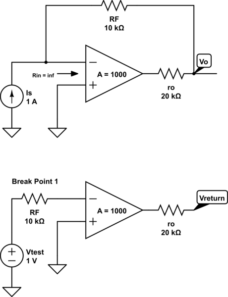
I have been having trouble finding the loop gain (Aβ) of the following transimpedance amplifier:

simulate this circuit – Schematic created using CircuitLab
To find Aβ, the books I have looked at (Sedra&Smith as well as Razavi CMOS ICs), the following method is used:
- Break the feedback loop at any point (preferably at a point of infinite impedance)
- Place a test voltage at one side
- At the other side reconstruct impedance seen from the test voltage
- Eliminate the input source
- Loop gain Aβ will be the ratio Vreturn/Vtest where Vreturn is the voltage at the other side of the break point
I have tried the break point above for this circuit and as you can see above it doesn't give the right answer. For example, using that break point Aβ would be found to be:
\$ Vreturn/Vtest = \mu \$
However using method of finding separate A and β circuits:
\$ Vreturn/Vtest = \mu (R_f/(R_f+r_o)) \$
I find it easy to find loop gain Aβ using method of finding seperate A and β circuits, but would like to know how to apply the described method here. I have found the method successful in other amplifiers such as voltage, and transconductance amplifiers, but can't seem to figure out how to apply it here.

