1
\$\begingroup\$

schematic

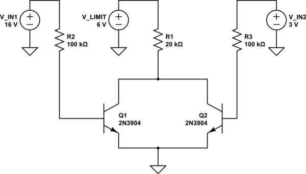
simulate this circuit – Schematic created using CircuitLab

Let's make everything ideal by ignoring the voltage drops:

  • Q1's allowed collector current is: 22.4 mA

  • Q2's allowed collector current is: 4.2mA

  • Total available: 300uA

I need to know if we have a limited current source and multiple collector are drawing current from it (as above), do each collector draw currents proportional to what they would've been drawing if they would be drawing from a non-limiting current source?

According to LTSpice, this will be around:

  • Q1's collector current: ~252 uA --> 300uA * 22.4mA / (22.4mA + 4.2mA)
  • Q2's collector current: ~47 uA

As LTSpice's own component library is different valued, and one might be comparing from another simulator that happens to be non-SPICE, these are just simple calculation from the numbers we have above. But if one were to add up the actual values in LTSpice (and other non-idealities), it really obeys this proportionality.

CircuitLab seems to give another result. Q1 apparently goes in Reverse Mode and everything adds up.

Intuition tells me that unless the difference in Q1 and Q2's "collector current allowed" is really big they will have nearly the same amount of current.

So which one should I trust?

I could also breadboard it, but I hardly think an example is a guarantee.

\$\endgroup\$
5
  • \$\begingroup\$ V_limit and the 20k ohm. I do not call that a limited current source. Think what happens if R1 (20kohm) was not there so both collectors were at 6 V. What would the collector currents be ? Now the same but with R1 there, what happens to the voltages at the collectors ? Instead of using a simulator sit back and use your brain to think about what will happen. Do a simple calculation. Try to understand what happens instead of relying on random formulas and simulator results. \$\endgroup\$ Commented May 7, 2016 at 13:48
  • \$\begingroup\$ If R1 was not there, Q1 will be drawing 22.4 mA in it's collector and Q2 would be drawing 4.2mA. Do you think you can actually draw 26.6 mA now that that's in SATURATION??. That's why I said "ALLOWED CURRENT". I think you guys are just comfortable in thinking, "this pulls it to voltage source; this pulls it down to ground", instead of thinking in terms of current limiters, which they are. \$\endgroup\$
    – Majin_Boo
    Commented May 7, 2016 at 15:06
  • \$\begingroup\$ Try breadboarding this and you'd see that the collectors are current limited. \$\endgroup\$
    – Majin_Boo
    Commented May 7, 2016 at 15:07
  • \$\begingroup\$ Try breadboarding this and you'd see that two 2N3904 transistors aren't perfectly matched the way they are in a simulator. \$\endgroup\$
    – The Photon
    Commented May 7, 2016 at 18:52
  • \$\begingroup\$ @Majin_Boo "If R1 was not there, Q1 will be drawing 22.4 mA..." If you know it all so well, why are you asking here ? No one ever talks about "allowed current" because it's a meaningless term. It's not like the resistor "allows" a certain current, it's a combination of resistor, voltage and transistor behavior resulting in a certain certain current flowing. But since you refuse to try and understand what the circuit is actually doing I'm done here. \$\endgroup\$ Commented May 7, 2016 at 19:14

0

Your Answer

By clicking “Post Your Answer”, you agree to our terms of service and acknowledge you have read our privacy policy.

Browse other questions tagged or ask your own question.