4
\$\begingroup\$

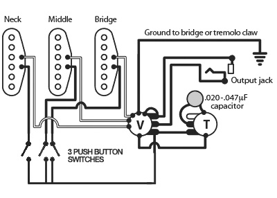
I'm working on a guitar, and the plan is to use three latching push buttons so that each pickup can be turned on and off individually. I'm fairly confident that the following diagram should work for that (Feel free to correct me) Wiring Diagram

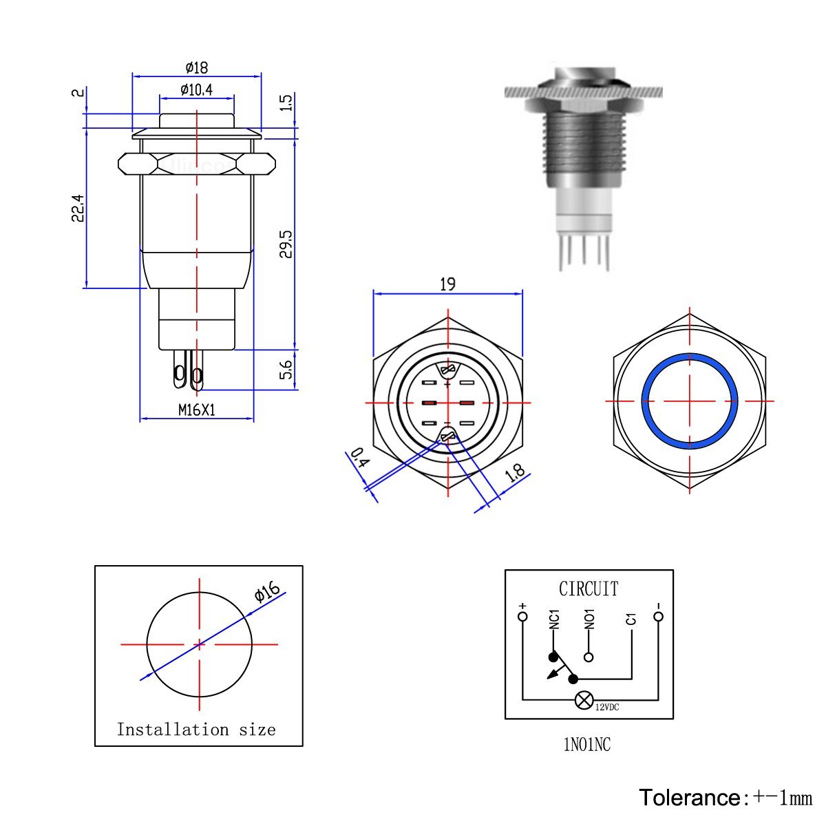
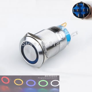
The buttons I want to use are these, which have a built-in LED when turns on when the button is pressed. Button

Which brings me to my question: Is there a way to power the LED? If I introduce a 9volt into the wiring, wouldn't that cause problems with the guitar's standard electronics?

\$\endgroup\$
13
  • 1
    \$\begingroup\$ Yes, you're right. You need 2-pole switches (two separate contacts) so can use one for the audio and one for the switching. You could use relays or an electronic solution but the mechanical option has the advantage that at least the pickups will still work when the battery goes flat. \$\endgroup\$
    – Transistor
    Commented Jun 5, 2016 at 18:37
  • \$\begingroup\$ Ok, so I'd be looking for DPDT ones then, right? To send the signal to ground? \$\endgroup\$ Commented Jun 5, 2016 at 18:41
  • 1
    \$\begingroup\$ I'd keep the indicator circuit electrically completely separate to avoid clicks on the audio. One contact to do the pickup switching, the other to connect battery positive (or negative, if you prefer) to the LED. \$\endgroup\$
    – Transistor
    Commented Jun 5, 2016 at 18:55
  • \$\begingroup\$ Would a typical double pull double throw be separate enough, you think? \$\endgroup\$ Commented Jun 5, 2016 at 19:00
  • 1
    \$\begingroup\$ In your diagram, what are the "V" and "T" circles ? \$\endgroup\$
    – dim
    Commented Jun 5, 2016 at 21:17

2 Answers 2

1
\$\begingroup\$

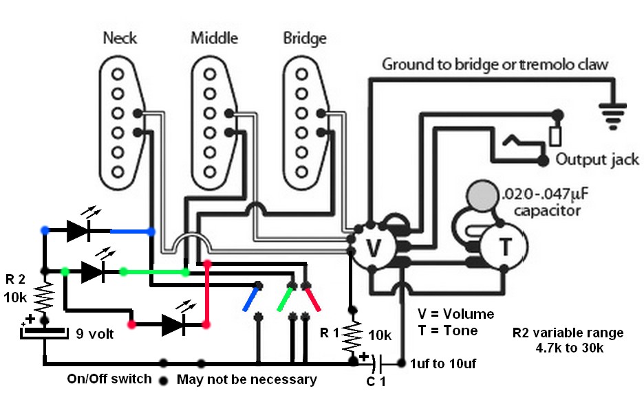
I am familiar with guitar pickups. I know your best method would be to use DPST switches.

But if you want to try this, I think it will work. When all Three switches are open there will be voltages across all 3 pickup heads. Going from battery B+, thru each LED, thru all 3 heads, and back to R1 to negative side of the battery, too low to turn on any LED.

When any switch is closed the voltage will be going thru R2, one LED, to a switch and back to negative side of the battery. Capacitor C1 and R1 will isolate the DC Voltage from the volume control to your amplifier. My only concerns are if the diodes conduct the signal from the unused pickups.

All of this circuit will have to be close to the shielding ground of the guitar to prevent AC hum pickup. The current draw, if all 3 switches are open may not be enough to drain the battery?? This is all dependent on your using magnetic guitar picks with an approximate 10k ohm reading.

I got to thinking if R1 is increase in valve up to a maximum of 47k your pickup heads resistance may not matter. enter image description here
\$\endgroup\$
1
  • \$\begingroup\$ Thank you for this! I actually reached out to the seller and they mentioned the top two pins are for the LED power,the bottom three control the circuit, and that those are isolated from each other. They also said anything under 12V will be OK for the LED so there must be a built in resistor. So I think we're good to go! \$\endgroup\$ Commented Jun 14, 2016 at 18:18
0
\$\begingroup\$

For completions sake, here's the DPDT version, notice the two sets of pins in the middle. Unlike the ones you link to, which have empty holes on the second set:
enter image description here

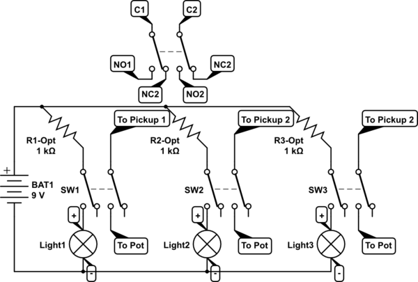
Wiring would be simple:

schematic

simulate this circuit – Schematic created using CircuitLab

The Resistors are optional, in case you need to reduce the current to the LEDs if they are too bright or drain your battery too long. Of course, at 9V, they may not light, as they are typically wired for 12V. For the LEDS, you wire the Battery Positive to the Common side, and the Normally Open to the Positive (+) of the LED, and the Negative (-) of the LED to the Battery.

\$\endgroup\$

Your Answer

By clicking “Post Your Answer”, you agree to our terms of service and acknowledge you have read our privacy policy.

Not the answer you're looking for? Browse other questions tagged or ask your own question.