0
\$\begingroup\$

I am trying to use a Photocoupler 4N-25 with an arduino uno r3.

I connected the collector to +5volts and the emitter to ditital pin 0.

Now, since there is no voltage applied to the gate and I haven't even connected the other side of the photocoupler (diode) with anything. Shouldn't it have an indication of LOW in the serial monitor? Instead it fluctuates between 0's and 1's.

I also gave it a try with the gate grounded, nothing...

I tried with a resistor to limit the current to the arduino, nothing...

Any suggestions?

EDIT

By trying out the circuit of @Passerby the input pin was high. when i turned the gate High the pin went low. All is good so far.

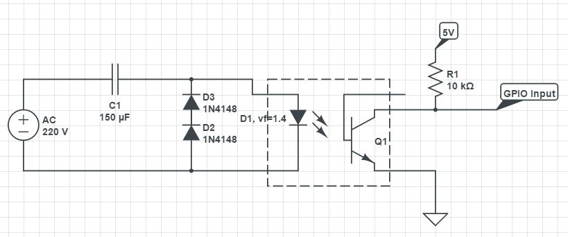
what i want now is this depicted below.

enter image description here

when i replace the opto-isolator with a simple led (D1) it works. i tried it out.

The problem now is that the led in the opto-isolator is not bringing the gate high. why is this happening.

keep in mind that i only want to use this opto-isolator for this circuit.

and correction the capacitor is 150nF

\$\endgroup\$
4
  • \$\begingroup\$ You should have pinMode(0,INPUT_PULLUP) and not pinMode(0,INPUT) in your setup() \$\endgroup\$
    – Roger C.
    Commented Jun 5, 2016 at 19:36
  • 1
    \$\begingroup\$ This is not a forum but a Q&A site. Please don't change the question after it has been answered; if you have a new question, ask a new question. \$\endgroup\$
    – CL.
    Commented Jun 5, 2016 at 20:52
  • \$\begingroup\$ You have not accounted for both AC cycles, and have probably killed your diodes or your optocoupler. Put another 1N4148 in parallel with the 2 you have, but reversed. And for God's sake reduce your capacitor to 1 uF or less. \$\endgroup\$ Commented Jun 5, 2016 at 20:57
  • \$\begingroup\$ since the vf of the photocoupler led is 1.4 v and 10mA. then R (instead of a capacitor) would be 22000 ohms. if you set R as the reactance Xc with frequency 50hz and solve for C = 145nF~150nF. it works for a normal LED why not for a photocouplers LED of same specs? \$\endgroup\$ Commented Jun 5, 2016 at 21:08

1 Answer 1

2
\$\begingroup\$

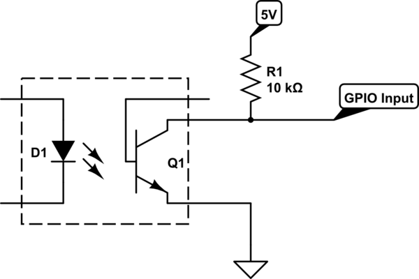
Typical wiring for a on/off digital signal from an optocoupler is this:

schematic

simulate this circuit – Schematic created using CircuitLab

Pull-up to VCC, most likely 5V for most Uno R3. The pull-up gives it a known state of HIGH when the optocoupler's LED isn't on. When the LED is on, the optocoupler's transistor turns on, pulling the collector towards ground, giving a LOW signal.

Alternatively, wire the collector to the GPIO with the pinMode(x,INPUT_PULLUP) mode enable, using the internal ~47kΩ pull-up resistor. Essentially the same thing.

This is a typical open-collector setup for digital logic.

The Way you had it connected, with the emitter to the GPIO, is a emitter follower, and will show either 5V when the LED is ON or FLOATING when the LED is OFF. A Floating input will not have a fixed state, and will float between states, like an antenna. Use the wiring above instead.

\$\endgroup\$
1
  • \$\begingroup\$ the two diodes in series are there to bring the forward to 1.4 volts. The circuit works with an led. \$\endgroup\$ Commented Jun 5, 2016 at 20:09

Your Answer

By clicking “Post Your Answer”, you agree to our terms of service and acknowledge you have read our privacy policy.

Not the answer you're looking for? Browse other questions tagged or ask your own question.