0
\$\begingroup\$

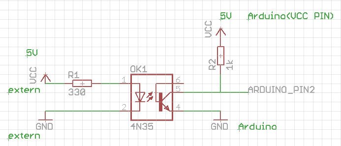
I trying to interface the arduino digital pins through an optoconnector attached to an LED of a consumer electronic device. I have bought the recommended component for this.

Before I would even get to the point of hooking up to the device's led to the 4N35 I already have a serious problem.

I tried to emulate the device here with standard +5V LAB supply.

Once the 4N35 opens it gets stuck in that state, even after removing the external power the arduinos pin is still pulled down to the GND like the switch would be closed.

Obviously I could use relays for this input detection but I rather not since the device will be usually providing +5V (aka being on).

Any help appreciated!

4n35 ardu

\$\endgroup\$
7
  • 2
    \$\begingroup\$ I'm confused "Once the 4N35 opens it gets stuck in that state" then you say "the arduinos pin is still pulled down to the GND like the switch would be closed" - those are contradictory so please try and say what you mean. \$\endgroup\$
    – Andy aka
    Commented Jun 14, 2016 at 12:27
  • \$\begingroup\$ Isn't this the way it should be working? When the 4N35 turned off the arduino PIN2 is connected to +5V through the 1k resistor, once it opens it would connect pin2 directly to the GND. The problem is that once this is done it will not go back to the previous state. \$\endgroup\$
    – Defiler
    Commented Jun 14, 2016 at 12:41
  • \$\begingroup\$ make sure you know which way round your ohm-meter works you want + to pin 5 and - to pin 6 when activated you should read very low resistance when not - high resistance if you do get polarity wrong, the low resistance won't be quite so low - This just might be the problem \$\endgroup\$
    – Defiler
    Commented Jun 14, 2016 at 14:32
  • \$\begingroup\$ "The problem is that once this is done it will not go back to the previous state." With the configuration shown the Pin 2 signal will be the inverse of that on the left end of R1. When R1 is pulled high Pin 2 will be pulled low. When R1 is disconnected Pin 2 will be pulled high by R2. "Once the 4N35 opens it gets stuck in that state, even after removing the external power the arduinos pin is still pulled down to the GND like the switch would be closed." That's not right. You have a weird fault or your wiring is incorrect. \$\endgroup\$
    – Transistor
    Commented Jun 14, 2016 at 15:29
  • \$\begingroup\$ Thanks, could you post a correct one? I don't care if it's low or high signal to the arduino I can just assign which ever function want to the 2 states. Thank you! \$\endgroup\$
    – Defiler
    Commented Jun 14, 2016 at 15:44

1 Answer 1

1
\$\begingroup\$

No it was NOT correct, @transistor was absolutely right with his answer.

ardu switch

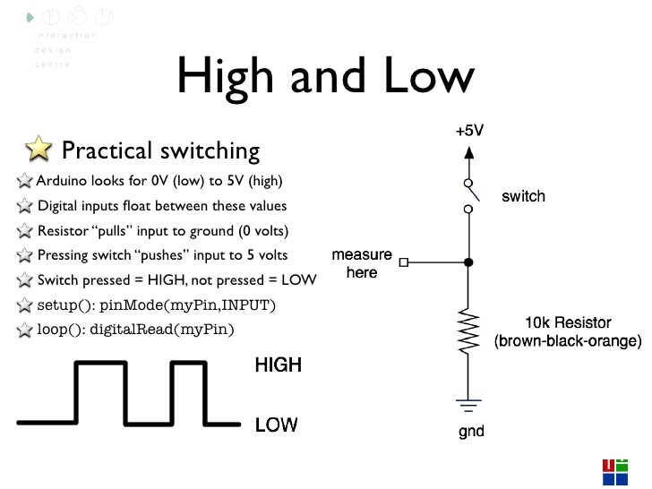
With this reverse schematic the arduino is pulled to low constantly by the 10k unless the opto connector is on and closes the switch.

Whoever made that first wrong circuit diagram it should be removed from google because it can mislead a lot of people.

Unfortunately regardless all the hassle to get this to work, when it is connected to the actual consumer device it makes that circuit malfunction having the 2N35 opto attached to the LED inputs.

When I connect it (with or without the 330 Ohm resistor on 1-2 legs) it causes the device to blink once then not to react to anything (like the power on button) until I remove the attached 2N35.

Maybe it takes up too much load and the circuit misbehaves. Can somebody share ideas regarding this? Is there a component similar to the 2N35 with lower resistance which will be invisible for the host device and does not cause it to malfunction? I assume that is the problem here.

One ugly hack I could do for this is to glue a foto-resistor in front of the LED but since this is a multicolor LED in the consumer device it could not determine whether it is Green or Red.

\$\endgroup\$
1
  • \$\begingroup\$ This is both not an answer - as you are asking a question, it should be an edit to your question - but more importantly its conclusion is also incorrect. There really isn't much difference as you imagine between the circuits, and the first one is not incorrect - what is different is the state of the output when the LED is off, but both are valid. Because you indicate this is feeding an Arduino, one would assume you can change the input sense at will. \$\endgroup\$ Commented Jun 15, 2016 at 13:56

Your Answer

By clicking “Post Your Answer”, you agree to our terms of service and acknowledge you have read our privacy policy.

Not the answer you're looking for? Browse other questions tagged or ask your own question.