0
\$\begingroup\$

I am finding it hard to find a detailed step by step process. Do I have to make a truth table?

Workings so far: I can guess that I would need 2 4-16 decoders, which share the 5 inputs of the required 5-32 decoder, and gives 32 outputs. But that leaves me with 1 extra input that I can't cater to, where is it going to come from?

\$\endgroup\$
0

1 Answer 1

1
\$\begingroup\$

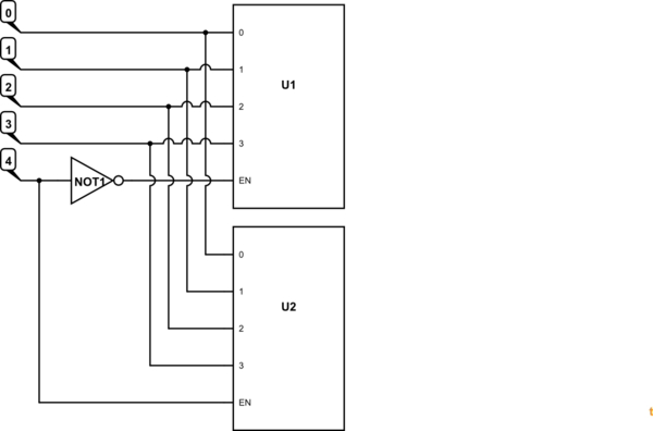
schematic

simulate this circuit – Schematic created using CircuitLab

Figure 1. 5-bit decoder inputs.

  • Use the enable bit as the fifth bit.
  • When '4' is low U1 is enabled.
  • When '4' is high U2 is enabled.
\$\endgroup\$
3
  • \$\begingroup\$ Now you did the homework for @studious \$\endgroup\$ Commented Jun 19, 2016 at 21:32
  • \$\begingroup\$ Homework detector not switched on. Oops! \$\endgroup\$
    – Transistor
    Commented Jun 19, 2016 at 21:44
  • \$\begingroup\$ that's not 5-32, and it doesn't allow activating all the outputs as only one decoder is active at a time \$\endgroup\$ Commented Jun 16, 2019 at 1:20

Not the answer you're looking for? Browse other questions tagged or ask your own question.