I have built a little circuit using a Atmega328P to drive a DD-32645C-2A display using a connector board. The display uses a SSD1303 driver.
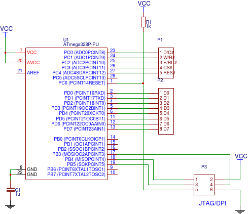
So here is my circuit:
Pretty straight forward, I think. I use the C port to set the control pins of the display and the D port to send commands/data. Here is the code I programmed onto my MCU:
#include <avr/io.h>
#define F_CPU 8000000UL
#include <util/delay.h>

void inital(void);
void write_c(unsigned char ins_c);
void write_d(unsigned char ins_d);

int main(void)
{
    // set ports D and C as output
    DDRC = 0b11111111;
    DDRD = 0b11111111;

    inital();

    while (1)
    {
    }
}


void inital(void)
{
    PORTC &= 0b00000000;    // reset display pins
    _delay_ms(150);         // delay 150ms for reset
    PORTC |= (1 << 5);      // set RES to high

    write_c(0xAE);
    write_c(0x81);
    write_c(0xAF);
    write_c(0xA8);
    write_c(0x3F);
    write_c(0xA0);
    write_c(0xD3);
    write_c(0x00);
    write_c(0x40);
    write_c(0xC8);
    write_c(0xDA);
    write_c(0x12);
    write_c(0xD9);
    write_c(0xF1);
    write_c(0xDB);
    write_c(0x49);
    write_c(0xA4);
    write_c(0xA6);
    write_c(0xAF);
}


void write_c(unsigned char ins_c)
{
    PORTC = 0b00010100;     // set pins for sending commands
    PORTD = ins_c;
    PORTC = 0b00011111;
}

void write_d(unsigned char ins_d)
{
    PORTC = 0b00010101;     // set pins for sending data
    PORTD = ins_d;
    PORTC = 0b00011111;
}
Also not to complicated, I think. I set up my C and D ports as outputs and call my initialization function. This function resets the display and sends a series of command to set it up(I simply copied this routine from the display's datasheet). The other two functions simply send a byte of data using port D.
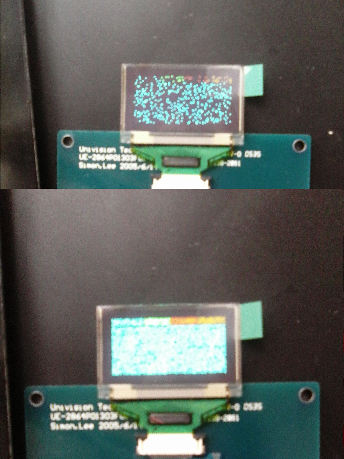
Now here's my problem: The setup routine seems to work fine, but my display looks like this(I apologize for my bad camera):
The first picture shows what I got initially, which is not really convincing. Now, after double and triple checking all of my connections and code for errors, I accidentally forgot to reconnect the VDD power(3.3V) to the connector board, which drives the display driver's logic(see page 5 of the connector board datasheet in the comment). And that result is shown on the second/lower picture above.
Still not perfect, but much closer to the desired effect. There should be on big blue rectangle and four smaller colored ones at the top. But still some pixels won't light up.
Has anyone a idea what is going on here? Not connecting the VDD pin for the display driver's logic doesn't make any sense to me, but makes my display work better.


write_d). \$\endgroup\$