3
\$\begingroup\$

i'm facing the problem to turn a 9V (battery) powered device OFF using the output of a 3.3V based microcontroller. To do this i already threw together the following circuit (which works - assuming i drew it correctly...) EDIT: oops, the pulldown resistor R5 should of course not be 220ohms but something bigger. enter image description here
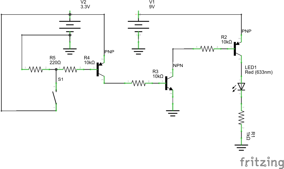
The device I have to switch off is represented by LED1 and the digital Output from the microcontroller by switch S1. The problem this circuit gives me is the high voltage drop of about 1V which would probably toggle the device to battery-low mode. Is there any alternative circuit i can use that has a very low voltage drop? And also, the design should be "fail safe", so the microcontroller could die/become unresponsive/whatever and in most cases the device will still be functioning like in my example above. Thanks

\$\endgroup\$
2
  • 1
    \$\begingroup\$ Fail-safe is a complex requirement on its own. I suggest an external watchdog timer that will put the output in your desired state (hardware, not firmware) or at least use an on-board watchdog timer and charge pump so sticking in either state won't put the output in an undesired state. The effort should be commensurate with the cost of a failure- something that could conceivably burn down a building or harm someone should generally not be left to firmware or hardware with a potential single point of failure. \$\endgroup\$ Commented Oct 27, 2014 at 15:31
  • 1
    \$\begingroup\$ Could you use a simple NPN low side switch, and an external pullup resistor (to 3.3v) at the micro, so that anytime the micro is either floating the pin or driving it high the transistor is on, and only driving low (presumably from your program) will turn it off? You can also see if the micro has a watchdog timer you can activate - but it still won't be foolproof. \$\endgroup\$ Commented Oct 27, 2014 at 16:46

1 Answer 1

10
\$\begingroup\$

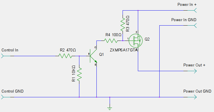
Change your load-driving PNP for a P-channel MOSFET. Also, you want a pull-up resistor on the gate of that MOSFET to ensure it switches itself off when the NPN switches off.

The NPN should also really have a pull-down on its base to keep it off when its input is HiZ or disconnected.

This is a circuit I use all over the place:

enter image description here

\$\endgroup\$
3
  • \$\begingroup\$ i'll give it a try and see if i can get a p-ch. mosfet, thanks for your answer. \$\endgroup\$
    – Stefan
    Commented Oct 27, 2014 at 15:25
  • \$\begingroup\$ one more thing, do you know what kind of voltage drop to expect from your setup? \$\endgroup\$
    – Stefan
    Commented Oct 27, 2014 at 15:28
  • \$\begingroup\$ That depends on the current draw. The MOSFET will be seen as a small resistor (ideally a few mΩ), so usually very little voltage drop. \$\endgroup\$
    – Majenko
    Commented Oct 27, 2014 at 16:11

Your Answer

By clicking “Post Your Answer”, you agree to our terms of service and acknowledge you have read our privacy policy.

Not the answer you're looking for? Browse other questions tagged or ask your own question.