1
\$\begingroup\$

I'm currently designing a (fairly easy) circuit, which is powered by an ordinary 12V Power Supply. To flash the embedded µC and/or get debugging output, I use an onboard USB-UART-Interface.

To make the circuit programmable even when not connected to 12v, I want to power the circuit via USB.

Therefore my question is whether it's safe to connect USBVCC to the 12v rail over just a single Diode (e.G. 1N4148)? The voltage drop across the diode is not a problem in my case, since they only feed a LDO which requires about 4V: My planned circuit
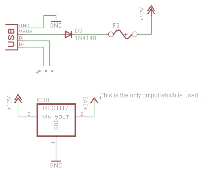
Most circuits I saw online (e.G. the Arduino UNO Power Supply) use an OpAmp & FETs to switch between the power sources, but from my understanding, the Circuit shown above should do the job, as long as the Voltage Drop across the Diode is no problem.

If the suggested circuit is ok to use, I'd like to get a few advises on how to make the circuit more safe to use. If the diode ever fails, the circuit would kill the USB Controller of the Computer it's connected to (best case) or even kill a whole x-k$ notebook.

I think an 5V-Varistor and an additional fuse should to the 'additional safety' (see second circuit), but would the varistor & fuse would react fast enough to protect the USB-controller from being damaged? enter image description here
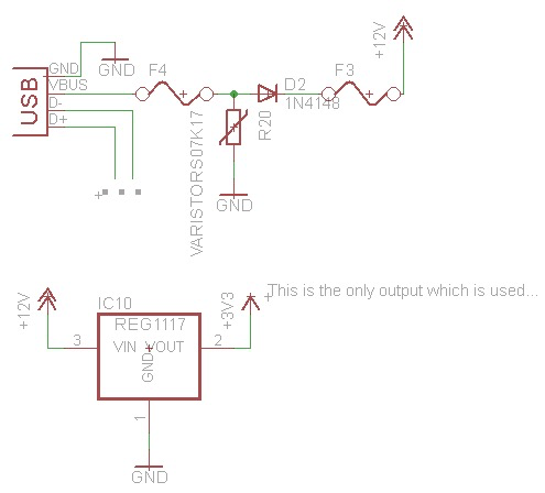
(P.S.: Yep, i have caps for the LDO, just left them out here for simplicity)

\$\endgroup\$
1
  • 1
    \$\begingroup\$ If your power draw is very low, then the 1N4148 might be appropriate. Otherwise, you should choosing a Schottky diode with the appropriate current rating. These diodes have a lower forward voltage drop than silicon PN-junction diodes do. And are commonly used in power applications for this reason. \$\endgroup\$ Commented Jul 2, 2016 at 1:52

1 Answer 1

1
\$\begingroup\$

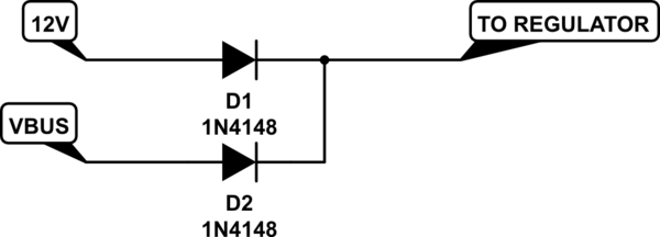
This is actually fairly common, though you'll also want a diode in line with your 12V supply as well. It is called "diode auctioneering" in the power electronics industry and I've seen it used in an extremely high power system (megawatt range) to switch between kilovolt-range redundant DC power sources.

schematic

simulate this circuit – Schematic created using CircuitLab

The varistor should be sufficient as protection in my opinion, though you may want to consider a TVS diode as well. It will only be needed for the brief instant that the diode is reverse-conducting, though it may not be necessary. When the 12V connects (and the 5V is already there), the diode takes a bit to start blocking (reverse recovery time) and so the 5V line will see a burst of 12V, but it may actually be able to absorb that since it will quickly be removed. Never hurts to be safe though with the protections.

You will also want to make sure your regulator will behave nicely with the sudden jump up to 12V. It could produce a transient on the 3.3V line, depending on the type of regulator you are using. AFAIK linear regulators (like the 1117) are usually pretty good at this, but I'd check anyway.

\$\endgroup\$
4
  • \$\begingroup\$ Thanks for your answer, i'll check whether the 1117 will be happy with these voltage jumps. So the additional diode prevents the 12v circuitry from 'being powered' via USB? If the circuit would never be powered solely from usb, it wouldn't be necessary? (Thats just an theoretical question to understand the why!) \$\endgroup\$
    – tillz
    Commented Jul 1, 2016 at 23:33
  • \$\begingroup\$ Technically yes, you don't need the 12V diode. However, I think it adds flexibility since you could power it with voltages lower than 5V if you wanted to via the 12V line (with an LDO it would be the 3.6V-12V range if you used a schottky diode). It just feels incomplete to leave it out and if you're not attempting to cut pennies in mass production, I can't see a reason not to have the flexibility. \$\endgroup\$ Commented Jul 1, 2016 at 23:35
  • \$\begingroup\$ Yeah, of course, I just asked to understand what's the purpose of this additional diode. I'm totally with you, that this is the cleaner and more flexible solution! \$\endgroup\$
    – tillz
    Commented Jul 1, 2016 at 23:40
  • 1
    \$\begingroup\$ Another possible reason to put it in there is so that you don't back-power the 12V supply circuitry when the 12V supply is plugged into your device, but the 12V supply itself is turned off (i.e. unplugged). Some badly designed (or simply cheap) supplies won't like that very much. It might start drawing tons of current from your VBUS, depending on their design (or it might do nothing and behave nicely). \$\endgroup\$ Commented Jul 1, 2016 at 23:41

Your Answer

By clicking “Post Your Answer”, you agree to our terms of service and acknowledge you have read our privacy policy.

Not the answer you're looking for? Browse other questions tagged or ask your own question.