4
\$\begingroup\$

I want to measure the Mains voltage (230V/50Hz) using an ADC channel from a microcontroller.

This is my current approach ...

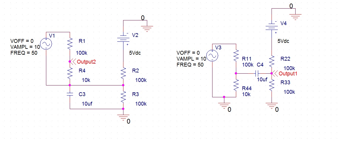
Below I have two schematics that add two voltages (one direct, one alternating).

Added to that, the both the AC and DC signals are going through voltage divider, but that isn't important.

I'm guessing that the output voltage on the second schematic is lower because of the impedance of the capacitor?

Schematics

\$\endgroup\$
3
  • \$\begingroup\$ Is that wire from R2 connected to R4 base? \$\endgroup\$
    – MaMba
    Commented Jul 6, 2016 at 15:53
  • \$\begingroup\$ What are you trying to do? Bias an AC signal to +5V/2 for an A/D converter? What frequency and what voltage? \$\endgroup\$
    – Transistor
    Commented Jul 6, 2016 at 16:06
  • \$\begingroup\$ Basically, I want to measure the Mains voltage (230V/50Hz) using an ADC channel from a microcontroller. \$\endgroup\$
    – C Cezar
    Commented Jul 7, 2016 at 11:40

4 Answers 4

4
\$\begingroup\$

If you only want to monitor the MAINS VOLTAGE, then you don't need to convert the entire sinusoidal waveform, add offset, etc. etc. You seem to be asking the wrong question.

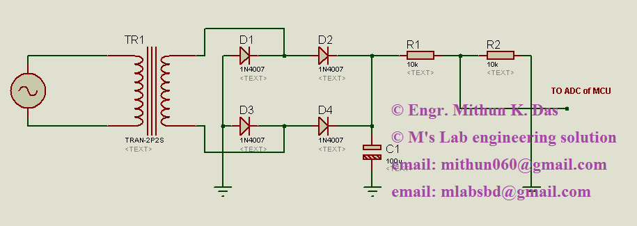
The common way of monitoring mains voltage is to FIRST ISOLATE the voltage with a transformer. This could be a very small transformer as found in a discarded wall-wart power supply, etc. Then rectify and integrate (filter) the voltage so that you have a DC voltage that is faithfully proportional to the mains voltage. This DC voltage can be simply scaled with a voltage divider, perhaps a potentiometer, and fed directly into the ADC input.

Here is a typical circuit which is very good for monitoring mains voltage...

enter image description here

Ref: https://mlabsbd.wordpress.com/2013/11/16/how-to-measure-ac-voltage-with-micro-controller/

\$\endgroup\$
1
\$\begingroup\$

What is the correct way to add a direct voltage and an alternating voltage?

Added to that, the both the AC and DC signals are going through voltage divider, but that isn't important.

It turns out, from your additional information in the comments, that it is important:

Basically, I want to measure the Mains voltage (230V/50Hz) using an ADC channel from a microcontroller.

I think your question is really, "How can I (safely) add a half \$ V_{REF} \$ offset to a signal potentially divided from the mains voltage?"

What you seem to be proposing is

schematic

simulate this circuit – Schematic created using CircuitLab

Figure 1. OP's proposal. Note that there is no mains isolation.

If you are proposing the circuit of Figure 1 then I suggest that you redesign. There is no isolation between the mains and micro. At best you will have neutral voltage appear on your micro ground. Do not assume that this will be zero as any current flowing from other circuits through the neutral wiring back to the mains source will cause a voltage drop along the resistance of the cable.) A far more serious situation will arise if the live and neutral connections were swapped. In this case the micro GND will become live.

Also, since you seem to be in 50 Hz land it is likely that your mains voltage will be 220 to 240 V. In this case a single resistor may not have adequate voltage rating for the high voltage supply. Two series resistors would be required for the high-side resistor.
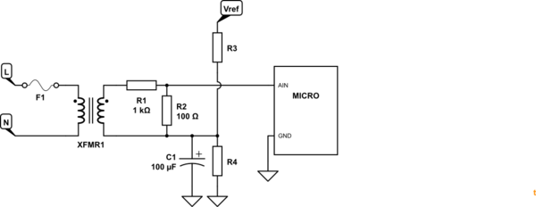
schematic

simulate this circuit

Figure 2. A small mains transformer of a few VA will provide isolation, a signal to work with and an easy means of adding a DC bias to the AC signal.

  • A 6 or 9 V transformer would be adequate for this circuit and provide a safe working voltage with no isolation or safety issues.
  • Size R1 and R2 to pull a few tens of mA from the transformer and reduce the peak voltage to the operating limits of the micro.
\$\endgroup\$
1
  • \$\begingroup\$ In my original post I did not mention anything about mains. The AC voltage that you see on the input side is actually the secondary of a transformer.(With an amplitude of 10V, which is a random value to easily check the divider is working). I did not include this information because I only wanted my question answered. Thank you for your answer, very thorough. I'm not that stupid to work with mains without isolation, maybe my question was. \$\endgroup\$
    – C Cezar
    Commented Aug 6, 2016 at 21:25
0
\$\begingroup\$

The usual way to do this depends on the frequency of the AC signal.

At low frequencies you might be able to use a summing op-amp circuit. This may limit the current that can be delivered at DC.

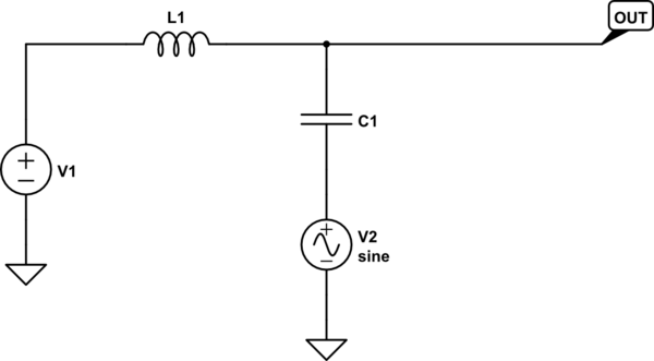
At RF frequencies you can use a bias tee. This is similar to your right side circuit, but removes unnecessary resistors and adds an inductor in the dc input path:

schematic

simulate this circuit – Schematic created using CircuitLab

\$\endgroup\$
1
  • \$\begingroup\$ Basically, I want to measure the Mains voltage (230V/50Hz) using an ADC channel from a microcontroller. I think the frequency is low enough. \$\endgroup\$
    – C Cezar
    Commented Jul 7, 2016 at 11:40
0
\$\begingroup\$

kindly tell me your device maximum and minimum voltage and your controller. here you have using STM32 controller check the following circuit. i have added ac voltage circuit, the output voltage is 3.3v when the input voltage is above 400vac. you need to reduce the resistor value for 230vac. and the output voltage is clamp up to positive side. in that "R" point you can use directly and check before with simulation software. enter image description here

\$\endgroup\$

Your Answer

By clicking “Post Your Answer”, you agree to our terms of service and acknowledge you have read our privacy policy.

Not the answer you're looking for? Browse other questions tagged or ask your own question.