2
\$\begingroup\$

Goal is to measure DC voltages in the 100-500VDC range, safely with a microcontroller (e.g. Arduino)

The particular application is to monitor the voltage of a large Lithium series parallel battery array with a total nominal voltage of 188 VDC. Measurement tolerance within a tenth of a volt is suitable for the intended application.

The purpose of the measurement is to utilize a microcontroller to automate the ON/OFF cycle of a battery charger via a low-voltage trigger relay.

I am looking for suggestions to a solution with measurement circuit simplicity and cost as considerations. This should be an integrated approach and avoid the need for discrete components such as transformers etc.

edit; it would be preferable to avoid using a traditional resistance based 'voltage divider' approach.
While this method is suitable for lower direct current situations, when dealing with high voltages things can get messy.
edit 2; added more language to clarify that, the solution should be integrated.

\$\endgroup\$
9
  • 1
    \$\begingroup\$ Take a look at linear optocouplers. They are optocouplers with one LED that illuminates two matched photodiodes. One photodiode is used as a feedback component to drive the LED to linearize things. One of the most important things is to hunt through the datasheets for the various application circuits, especially the HCNR200. Not all datasheets will contain all circuits but the circuits are interchangeable between components since they are all the same concept digikey.ca/en/articles/techzone/2012/dec/… \$\endgroup\$
    – DKNguyen
    Commented Jun 3, 2019 at 0:43
  • 1
    \$\begingroup\$ @DKNguyen: Please do not answer the question in comments, as this bypasses the normal review process for answers, as discussed in meta \$\endgroup\$
    – Dave Tweed
    Commented Jun 3, 2019 at 0:48
  • 1
    \$\begingroup\$ @DKNguyen: Then what was your purpose in making the comment? Comments are only supposed to be used to improve the post that they're attached to -- either asking for clarification or pointing out errors. \$\endgroup\$
    – Dave Tweed
    Commented Jun 3, 2019 at 0:54
  • 1
    \$\begingroup\$ Thanks for the link. Had previously considered the optocoupler, but the idea hadn't been corroborated, and also, hadn't found links to available parts to explore this as a viable solution. Appreciate the sharing of the link. Very informative and essentially answers the question. Agree with @DaveTweed, that the comment could have been posed as an answer. This would be accepted as a viable answer to the question! \$\endgroup\$ Commented Jun 3, 2019 at 1:07
  • 1
    \$\begingroup\$ @JohannessNilsson You might also consider a discrete relaxation oscillator that pulses an opto. You can count pulses, safely. Just another option. \$\endgroup\$
    – jonk
    Commented Jun 3, 2019 at 2:09

2 Answers 2

2
\$\begingroup\$

While others have suggested linear optocouplers and voltage dependent oscillators, I'll throw a very different method out as an answer to read high voltages with very high isolation.

I've used this in fully floating front ends up to around 56V. It should work for any voltage you can get a suitable transformer for.

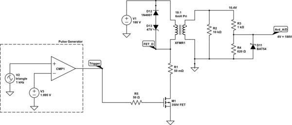
In the schematic below I've created a short pulse driving a FET. When the FET is ON, the transformer ratio is the attenuator. I've previously used small audio transformer because they have high inductance primaries, but I'd suggest you could use small DC-DC converter transformers just as successfully.

The transformer used here is most like this with an 18:1 turns ratio and about 6mH primary inductance. The transformer turns ratio is of course very stable with temp/time so makes an excellent attenuator.

schematic

simulate this circuit – Schematic created using CircuitLab

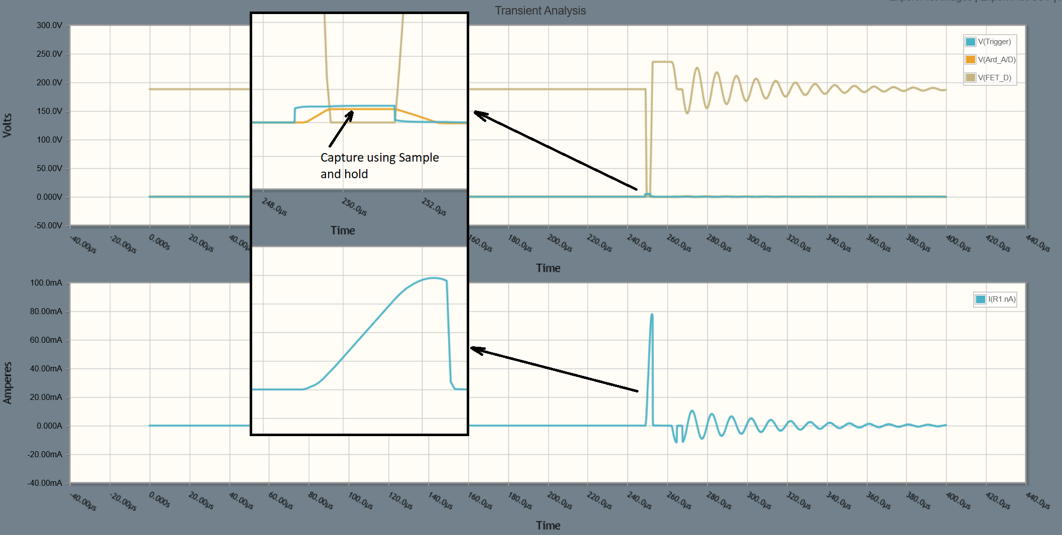
You could expect waveforms like this:

enter image description here

With the rather low primary inductance here, the current rises to 80mA quite rapidly. If you can find a transformer with a 20-50mH primary then the peak current is reduced and the time you can activate the FET made longer.

If you are using an Arduino then by default the A/D takes 104us per conversion. The pulse width in this circuit would therefore require a sample and hold to capture the stable output voltage. But if you can find a better transformer, then you might be able to hold the FET on for more than 15us so not require the external sample/hold (the ATMega328 has about 12us sample time for the internal S/H). It all depends on what you want as an acceptable input current peak in the transformer primary.

You obviously have to provide an isolated drive for the FET, but there are plenty of pulse transformers for this application that could be driven from the Arduino.

\$\endgroup\$
2
  • \$\begingroup\$ Consider the work you put into this answer worthwhile, and you are appreciated for taking the time to reply so thoroughly. This is a fine solution. However, the use of a transformer and the necessity for an accompanying S/H add's cost, and complexity. And the point of the question is to elucidate an integrated method that relies less on costly components, like discrete elements like transformers. Size is another factor. I will add an edit to the question to specify the desire for an integrated solution. \$\endgroup\$ Commented Jun 4, 2019 at 20:35
  • 2
    \$\begingroup\$ @JohannessNilsson I'd suggest there are no integrated solutions to measure up to 500V (other than perhaps a multimeter) as a floating measurement system. Hence the reason that the solutions offered are all purpose designed and requiring calibration. \$\endgroup\$ Commented Jun 4, 2019 at 21:04
1
\$\begingroup\$

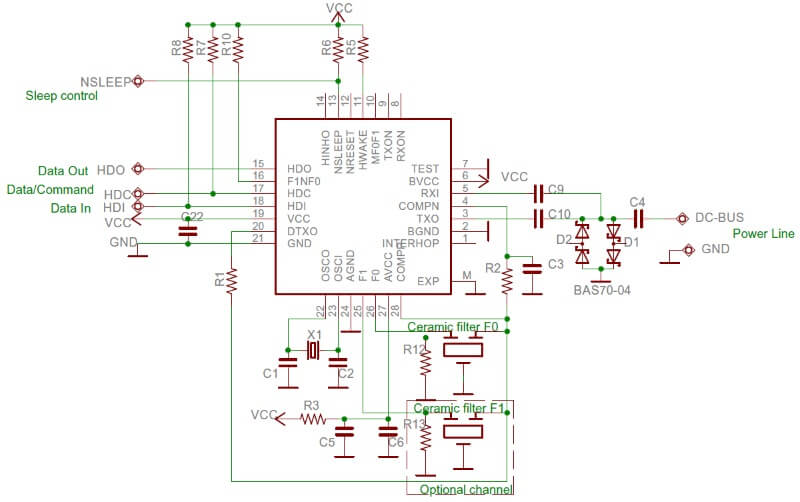
An integrated solution was identified and a customized implementation is being developed. The solution was the DC-BUS SIG60 system by Yamar Electronics. The SIG60 integrates between battery cells, forming a coms network though the cells of the battery pack, literally as the name implies on the DC bus. The SIG60 IC relays the relevant battery health information to the control systems. This solution significantly reduces the amount of wiring, enabling safe and highly accurate monitoring of each individual cell.

SIG60 Schema

\$\endgroup\$

Your Answer

By clicking “Post Your Answer”, you agree to our terms of service and acknowledge you have read our privacy policy.

Not the answer you're looking for? Browse other questions tagged or ask your own question.