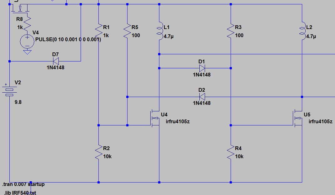
I'm working on a group project, where for one part of the circuitry we have a "Royer Oscillator", which can be turned on/off via an N-channel MOSFET (IRFU4105ZPBF) at the input (whose gate is connected to an Arduino). The second part of the circuitry (not included in the image below), is essentially the filtering stage where we filter out desired frequencies.
The problem I'm having with this implementation is the MOSFET configuration (top left, disregard the diode), where the drain is connected to the supply, and the source is connected to the load (the rest of the circuit), however I'm not sure if this is the right configuration since when we build the circuit, it doesn't work (the MOSFET wouldn't turn on), and even the simulation has next to no current at the source, which leads me to think that it should be connected to ground, and the drain going from the Power Supply -> to the rest of the circuit?
Essentially my questions are:
- Why am I getting next to no current at the source?
- Is the MOSFET connected properly?
- Can I have the drain connected to the supply, then have it connected to the rest of the circuit?
The individual MOSFET works by itself in turning on an LED, with the source to ground, and the supply coming through a resistor -> LED -> drain.
Most MOSFET circuits I've come across have the source going to ground, with the load coming from the drain, though I have come across others with my configuration below, so I'm unsure which is the correct one?

