0
\$\begingroup\$

I've been trying to teach myself about potentiometers and how they can be used as voltage dividers. I bought some Alpha 10k linear pots to use in a really basic test circuit. I intended to connect the pot to my breadboard but unfortunately it doesn't fit so I've soldered some spare jumper wires to the pins of the pot.

In my circuit I have power from my Arduino Uno board (3.3v) connected to the leftmost pin on the pot and the other outer pin on the right is connected to ground. The middle pin (which I've assumed is the wiper) is connected to ground as well. When I measure the voltage between the two outer pins it's consistently about (3.2v) as I would expect but when I measure the output voltage between the wiper and ground it's either 0 or moves randomly between different values regardless of where I've turned the knob to. I'm wondering if I've misunderstood how the pot should be wired in this configuration or if it's just a case of bad soldering?

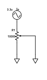
Circuit diagram

\$\endgroup\$
3
  • 3
    \$\begingroup\$ Here's your problem if you want a voltage divider: "The middle pin (which I've assumed is the wiper) is connected to ground as well." \$\endgroup\$
    – winny
    Commented Jul 24, 2016 at 13:58
  • \$\begingroup\$ Ah ok. So if I just want to measure the output voltage what should I connect the wiper to? Thanks for taking the time to answer. \$\endgroup\$
    – q4758u
    Commented Jul 24, 2016 at 14:00
  • \$\begingroup\$ Start with a new potentiometer, and connect the wiper only to the multimeter. \$\endgroup\$
    – pjc50
    Commented Jul 25, 2016 at 7:58

3 Answers 3

3
\$\begingroup\$

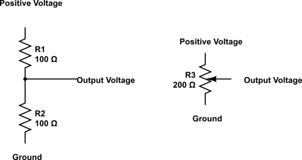
A potentiometer works in the same way as a simple two resistor potential divider, so here on the left is the equivalent of the schematic on the right showing a potentiometer. The middle output being the wiper of the potentiometer. On the physical potentiometer itself the middle pin is usually the wiper but I would recommend that you check that with a data sheet for the potentiometer.

I hope that this clears up the connections and just for extra knowledge here is a formula which will work to calculate the output voltage from the resistance of the two resistors either side of the output:

$$\mathrm{Voltage\space Out} = \mathrm{Voltage\space In} \times \left(\frac{R_2}{R_1+R_2}\right)$$

schematic

simulate this circuit – Schematic created using CircuitLab

\$\endgroup\$
8
  • \$\begingroup\$ I've had a look for the data sheet but I'm not having much luck. Here is a link to the site I bought it from: maplin.co.uk/p/… If I was to connect a resistor between the wiper and ground would the output voltage appear across the resistor? Thanks everyone for their help so far. \$\endgroup\$
    – q4758u
    Commented Jul 24, 2016 at 14:22
  • \$\begingroup\$ Okay, I have had a look but I also can't find one so the next best thing I can recommend is using a multimeter. If you have one I would measure the resistance of both of the outer pins relative to the central pin. If it changes when you twist the knob of the potentiometer relative to each other (the two values add up to 10k ohms) then the central pin would have to be the wiper. \$\endgroup\$
    – Nikita K
    Commented Jul 24, 2016 at 14:30
  • \$\begingroup\$ Ok I've just checked the middle pin against both of the outer pins and the value does change. I don't understand why there's no output voltage though. I've soldered and de-soldered 3 of the same pots like this and the results are the same each time. \$\endgroup\$
    – q4758u
    Commented Jul 24, 2016 at 14:40
  • 1
    \$\begingroup\$ Great. Now I'm getting the voltages I expected and I've learnt some useful theory. Thank so much for your help. \$\endgroup\$
    – q4758u
    Commented Jul 24, 2016 at 15:17
  • 1
    \$\begingroup\$ @NikitaK: $$ Vout = \frac {Vin \times R2}{R1 + R2}$$ Doing it your way would result in Vout being greater than Vin. \$\endgroup\$
    – EM Fields
    Commented Jul 24, 2016 at 15:33
3
\$\begingroup\$

The middle pin (which I've assumed is the wiper) is connected to ground as well. When I measure the voltage between the two outer pins it's consistently about (3.2v) as I would expect

And at that point, you will have damaged the potentiometer because when the wiper was physically close to the 3.3V end you would be shunting hundreds of mA through the carbon track and wiper and burning it.

when I measure the output voltage between the wiper and ground it's either 0 or moves randomly between different values regardless of where I've turned the knob to

Yes, that's what you might see when the wiper and or carbon track is damaged.

\$\endgroup\$
2
\$\begingroup\$

Inside a potentiometer

enter image description here

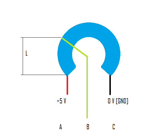
This is the anatomy of a typical potentiometer

The blue part has some fixed Length L such that the total resistance of this piece of metal is equal to 10 Kohms

enter image description here

When you want to measure the resistance between A - B you are not taking the total length of the piece of metal inside this potentiometer, instead you are able to vary this length using the knob.

And according to the electrical resistance equation the resistance you are measuring is now a function of length L between A - B

enter image description here

So, you should always use the wiper [Middle pin] to read the voltage with respect to the circuit reference voltage [GND]

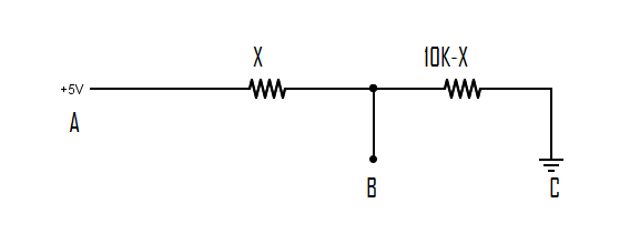
If you want an equivalent circuit for your potentiometer. You can think of this circuit

enter image description here

The total resistance between A - C is always 10Kohms but the one changing is the resistances between A - B and B - C

\$\endgroup\$

Your Answer

By clicking “Post Your Answer”, you agree to our terms of service and acknowledge you have read our privacy policy.

Not the answer you're looking for? Browse other questions tagged or ask your own question.