1
\$\begingroup\$

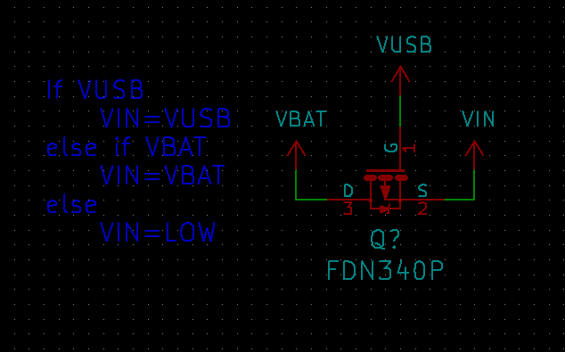
I've 'designed' this power source selecting circuit.

schematic

VIN is the output of the circuit. VBAT will have a voltage of 3-4.2V when connected. VUSB will have a voltage of 5V when connected.

The idea is for VUSB to provide all of the power when it is connected, and VBAT to supply power when VUSB isn't connected.

Will this design work as intended? Do I need any diodes to prevent power to go from VUSB->VBAT? Will I have a >0.1V voltage drop when either VUSB or VBAT is used as a source?

If not, is there a better or more proper way to achieve these goals?

\$\endgroup\$
6
  • 1
    \$\begingroup\$ The gate of a MOSFET is very close to a perfect insulator. So, no. \$\endgroup\$ Commented Jul 26, 2016 at 1:11
  • \$\begingroup\$ Sorry, but which question is that the answer for? \$\endgroup\$ Commented Jul 26, 2016 at 1:12
  • 1
    \$\begingroup\$ He intended to answer "Will this design work as intended?". VUSB is not physically connected to either VBAT or VIN. All VUSB will do is turn ON the MosFET. \$\endgroup\$
    – Mark
    Commented Jul 26, 2016 at 1:14
  • \$\begingroup\$ Alright. Glad I asked. So what is the way to actually do this? \$\endgroup\$ Commented Jul 26, 2016 at 1:14
  • 3
    \$\begingroup\$ This can be done with discrete parts, although I would normally now use an ideal diode controller; typical part: linear.com/docs/40584 \$\endgroup\$ Commented Jul 26, 2016 at 9:32

2 Answers 2

3
\$\begingroup\$

The short answer is no. The way you've drawn this circuit, if VUSB is present, VIN=VBAT, and if VUSB is not present, VIN=VBAT-Vbodydiode.

I'd say you need to do research into what a FET does. The best way to think about it is a unidirectional voltage-controlled switch. That is to say, current can always pass from Source to Drain through the body diode, and if there is enough voltage difference between the Gate and the Source, then current can pass either direction through the Drain and Source.

The way many systems accomplish what you're trying to do is to put a diode on each input rail, pointing toward your device. With this, power is drawn from whichever rail is higher (the channel of other diode will not be sufficiently enhanced). The only issue with this is that it will drop your voltage rail by 0.7V or so (depending on diode selection) and if you are drawing any appreciable current, you'll be heating that diode a lot (possibly causing a failure). I don't know your application, so I can't tell you if this solution would be appropriate or not.

Edit: While doing something completely unrelated, I happened across this schematic: http://www.synthrotek.com/wp-content/uploads/2014/08/DIRT_Schematic_2.2.pdf The two 1N418's in the bottom left corner are doing exactly what you're talking about. The 9V battery is always lower than the 12V coming from the EURO connector (note that this voltage is external knowledge, I am not able to tell that from this schematic alone), thus if the battery is the only power source present, it is used, but if the EURO power is there, then that will be used. Also note that the expected power dissipation in this device is quite low.

\$\endgroup\$
0
\$\begingroup\$

The simplest circuit is a manual DPST switch. Vin is connected to the "center/common" pin, Vbat is connected to NC pin and Vusb is connected to the NO pin. By toggleing the switch, you can select the source of the voltage.
If automatic operation is desired, then you have to implement the logic to disconnect Vin if both supplies are plugged in simultaneously. there are power sockets that have contacts that can close or open, when the corresponding plug is inserted.

\$\endgroup\$

Your Answer

By clicking “Post Your Answer”, you agree to our terms of service and acknowledge you have read our privacy policy.

Not the answer you're looking for? Browse other questions tagged or ask your own question.