Revison 1.3 (New circuit, more background information added, PCB made and tested, it WORKS)
Background: I would like to use a BeagleBone Black (=Minicomputer) for data acquisition in an automotive vehicle. It will be plugged into the OBD interface and will therefore be supplied by the 12.0 V - 14.0 V battery power / alternator.
The following specifications were defined:
- The minicomputer has to power on when the engine starts.
- The minicomputer has to stay alive when the engine goes out (e.g. new start/stop system in new vehicles at traffic jams)
- A clean shutdown (i.e. not cutting the power) should be made when no CAN or OBD messages have been received for 2 minutes.
- After the BeagleBone Black shutdown the power has to be cut to the automotive battery. (i.e. no further power consumption)
Actual progress/solution (Thanks to Olin and Dave!)
Two separate circuits. The trigger voltage indicates if the main switch is open or closed.
- Voltage sensing by TL431: When a voltage > 13.25 V was detected, the main switch will be opened by a P-Mosfet.
- A NP-MOSFET switches the power supply for the BeagleBone Black. When the battery voltage is above a specific threshold (e.g. 13.25 V) it closes the P-Channel (engine started, vehicle battery ~ 14.0V, the BeagleBone starts up). When the BeagleBone Black starts up, the internal 3.3 V closes also the N-channel MOSFET (This will keep the BeagleBone on, also when the car engine is out)
- When the engine is out, and the BeagleBone receives the poweroff system call, the BeagleBone powers down. The connection to the vehicle battery is cutted (No trigger voltage and no 3.3 V of the BeagleBone).
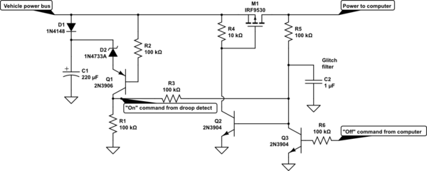
The circuit is shown below. Of course there is a protection circuit before and a step down converter after that part.
- MOSFET used: VISHAY SI4564DY-T1-GE3
- +12.0V = Vehicle Battery
- TRIGGER = When vehicle battery is > 13.25 V, this voltage will be pulled down
- VDD = Supply voltage for the BeagelBone Black (Goes into a step down converter)


