3
\$\begingroup\$

I'm taking an electrical engineering course and we are covering the effect of feedback on the bahaviour of amplifiers. I learnt the 4 basic topologies, and how with each configuration the feedback circuit can be replaced with a two-port network. It's summarised in this image I found on Wikipedia: enter image description here
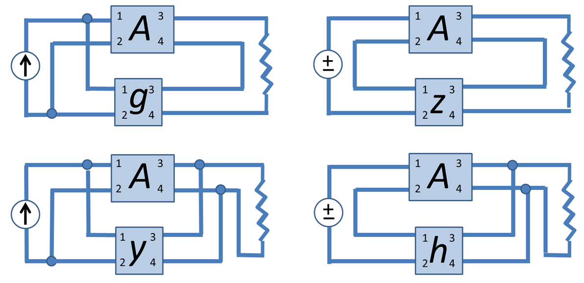
However, I can never figure out quite why these models are chosen. With the series-shunt connection on the bottom-right, for instance, my lecturer explained that the choice of hybrid parameters was because "the input is part of a series network and the output is part of a parallel network". Another source says something along the lines of "the feedback network and the main amplifier share the output voltage and input current".

Could you please try to get me to appreciate the choice of h, g, y and z parameters intuitively? Is it purely out of convenience or will it simply not work in any other way?

\$\endgroup\$
4
  • \$\begingroup\$ (1) Is "parameters" the right word in your second last sentence? Do you mean "topologies" or "configurations"? (2) Is your question "What determines the choice of topology for an application?" \$\endgroup\$
    – Transistor
    Commented Sep 24, 2016 at 9:55
  • \$\begingroup\$ @Transistor hi, thanks for the comment. No, I did mean to say "the choice of parameters". I didn't mean to ask how to choose feedback topologies when designing a circuit, but rather why we choose to use h-parameters for series-shunt, y parameters for shunt-shunt, etc \$\endgroup\$
    – Einheri
    Commented Sep 24, 2016 at 9:57
  • \$\begingroup\$ It might be worth clarifying that in your question and providing a link to the image source article. \$\endgroup\$
    – Transistor
    Commented Sep 24, 2016 at 9:59
  • \$\begingroup\$ @Transistor sure. ive done that, hope it helps \$\endgroup\$
    – Einheri
    Commented Sep 24, 2016 at 10:03

1 Answer 1

5
\$\begingroup\$

Even though it is hard to believe the two-port parameters are used to make life easier and give a simple representation of the feedback system.

Focusing on the simple representation, the strategy is as follows. First the common quantities on the input side and the output side have to be determined. Then suitable two-port parameters that have these as independent variables have to be found. For this step a table with all major two-port parameters could prove useful.

Looking at the series-shunt example (the right one in the bottom row) the networks share a common current at the input (I1) and have a common voltage at the output (V2). This results in h-parameters since they have I1 and V2 as independent variables.

For the shunt-series connection (left one in the first row) we find V1 and I2 as common quantities and consequently the g-parameters are used.

Ok, since I'm halfway through:

  • series-series (first row, right), I1 and I2 are in common, z-parameters
  • shunt-shunt (second row, left), V1 and V2 are in common, y-parameters
\$\endgroup\$

Your Answer

By clicking “Post Your Answer”, you agree to our terms of service and acknowledge you have read our privacy policy.

Not the answer you're looking for? Browse other questions tagged or ask your own question.