22
\$\begingroup\$

If connecting a pair of discrete MOSFETs back-to-back to create a bidirectional load switch, what's the practical difference between having them common-source versus common-drain?

In this particular case, I'm using a pair of p-ch FETs to isolate a battery from a load and also ensure that stored charge within the load can't return to the battery when switched off. I have a 3V6 battery so a logic level FET works fine. The PCB routing works best if I have common source, but I've seen both configurations used in literature.

In an integrated device I would imagine that there might be good reason to choose one over the other, since the common bulk silicon would most likely influence the choice. But with discrete parts there doesn't appear to be a clear reason for choosing one over the other, provided that the gate drive exceeds the body diode forward voltage drop as well as Vgth.

So are there reasons to specifically choose one of these configuration?

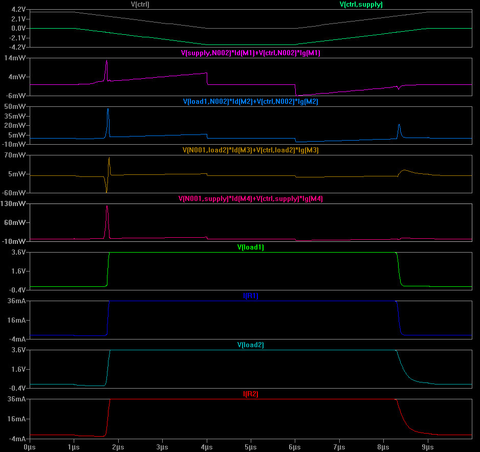
Given the base conditions: that the supply is greater than the FET Vgth plus a body diode forward drop; then either circuit works functionally. However, simulations indicate that there is some benefit to the common-source arrangement in that the switching transitions are faster so there is less power wasted in the FETs.

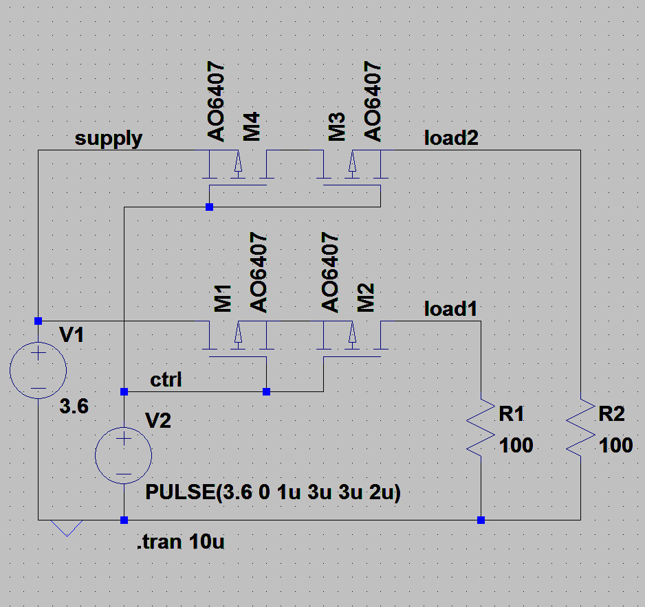
LTSpice schematic

Simulation Results

\$\endgroup\$
1
  • 5
    \$\begingroup\$ Please provide a schematic to prevent any ambiguity. \$\endgroup\$
    – jbord39
    Commented Oct 24, 2016 at 17:48

2 Answers 2

3
\$\begingroup\$

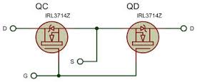
If you need to drive both MOSFETs from a common signal you have to tie the sources together or the body diodes will stop you turning them off. Every MOSFET has a diode in parallel with the drain and source electrodes.

enter image description here

The gate drive needs to either have a floating source applied between the common source and the common gate. Or have enough swing to guarantee enough bias for the entire swing of the input signal. The max Vgs will often prohibit that approach.

\$\endgroup\$
1
  • \$\begingroup\$ What about this approach? This doesn't use a floating source. electro-tech-online.com/articles/…. Are there unforeseen issues with this circuit? \$\endgroup\$
    – mrbean
    Commented Mar 16, 2023 at 22:35
3
\$\begingroup\$

I believe Kevin White's answer is partially incorrect (less partially that I origanally thought!, as well as showing N-channel fets). Neither way will work if the gate is not referenced to the floating sources unless the gates can goto the extremes of the signal (because of the diodes). Either way will work with that limitation.

In the common source case then as Kevin points out referencing the gates to the floating source allows switching of positive or negative voltages without limitations of Vgs

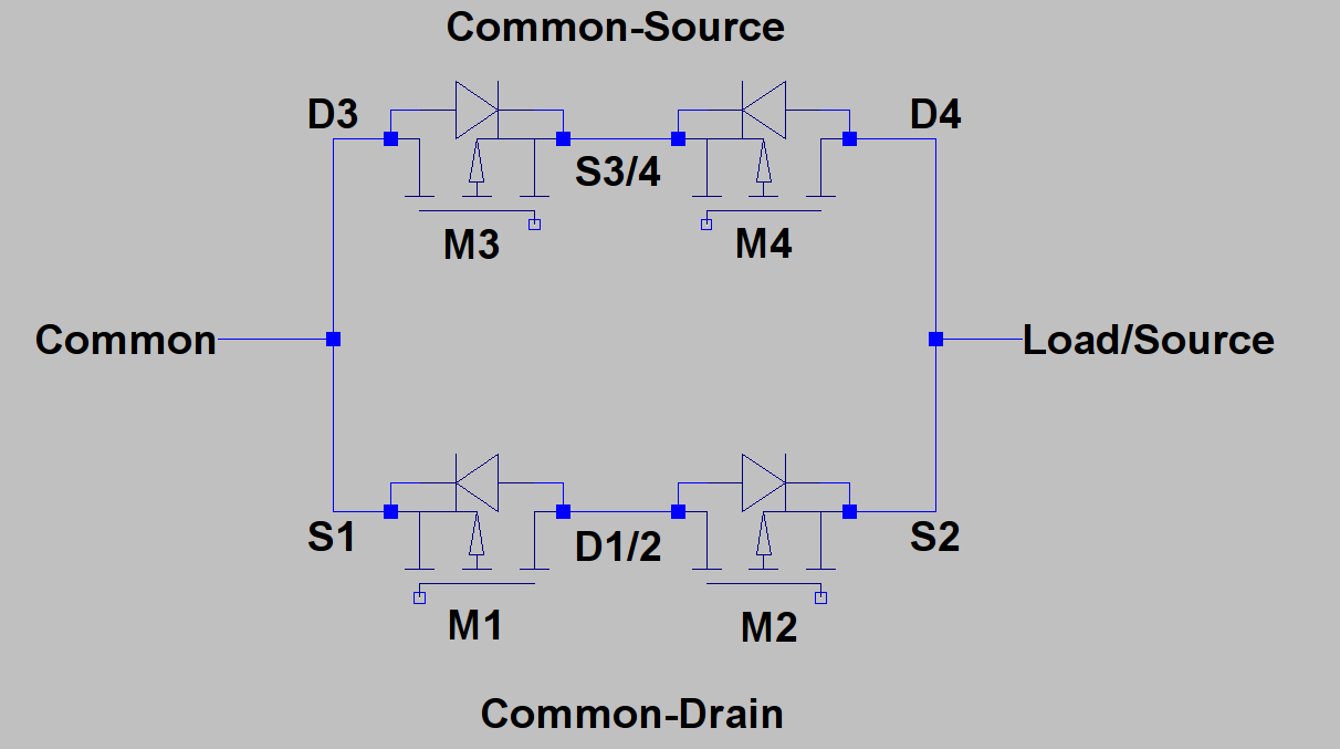
enter image description here

If the gates are referenced to the left hand side (Common) then it is clear that in the Common-Source case if the Load is more negative, then Vgate must be < than S3/4 which is only one diode drop from Common to turn on and >= Common to turn off. If the Source is more positive, then Vgate must be less than Common to turn on but >= S3/4 which is now one diode drop from Source.

In the Common-Drain case if the Load is more negative, then Vgate must be less than Load to turn on and >= Common to turn off. If the Source is more positive, then Vgate must be < Common to turn on and >= Source to turn off.

Assuming Common can only swing between Load and Source then Vgate has to be able to swing from Source to Load-G(thres) in either configuration. Apart from possibly the fact that in the Common-Drain case the two fets can share a heatsink I can see no reason to recommend it.

\$\endgroup\$
1
  • \$\begingroup\$ we have used common drain configuration, with one side Vin =12V , other side 3V to 8V. switched rail is working as expected \$\endgroup\$
    – user19579
    Commented Mar 22, 2019 at 5:45

Not the answer you're looking for? Browse other questions tagged or ask your own question.