In control systems theory when two systems with transfer functions \$ H_1(s)\$ and \$H_2(s)\$ are in series, equivalent transfer function is given as \$H(s)=H_1(s)H_2(s)\$. However if we have two RC filter in series, the equivalent transfer function is not a product of the two transfer functions of RC filter. It is indicated here Can you find the transfer function of two cascaded networks if you know their individual transfer functions?. My question is, does this means that transfer function \$ H_1(s)\$ and \$ H_2(s)\$ are calculated and these systems are always made such that input and/or output resistance of the other connected system doesn't make any influence on its performance? Or I am missing something? Or, when is it possible to do simple multiplication of the transfer functions?
3 Answers
In control systems theory when two systems with transfer functions \$ H_1(s)\$ and \$H_2(s)\$ are in series equivalent transfer function is given as \$H(s)=H_1(s)H_2(s)\$
This is definitely true but why would you consider two cascaded RC circuits as two separated systems!
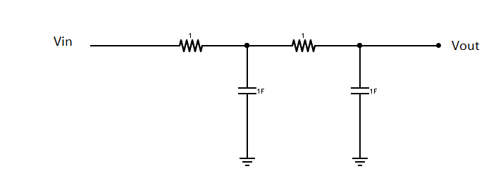
For example these two circuits are different from each other [One of them could be considered as two cascaded systems each of \$H_1(s)\$ and \$H_2(s)\$ while the other is considered as only one system with a transfer function \$H_3(s)\$
Circuit A:
Circuit B:
In circuit A you cant assume its just two cascaded RC circuits, since the first RC circuit affects the second RC circuit [THE LOADING EFFECT], you need to solve the whole circuit using any circuit theory to come with the differential equation representing the out/input relationship
While in circuit B you can assume these are two separate RC circuits such that none of them affects the other in this case you can do the multiplication
Circuit A transfere function would be
\$\frac{1}{R_1C_1R_2C_2S^2+(R_1C_1+R_2C_2+R_1C_2)S+1}\$
Whle circuit B transfere function would be
\$\frac{1}{(R_1C_1S+1)(R_2C_2S+1)}\$
Since i have assumed \$R_1 = R_2 = C_1 = C_2 =1\$ which are not practical values but just for demonstration
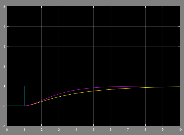
Now when examining the unit step response of both circuits you would definatily expect identical responses.
But in circuit A due to the loading effect the capacitor on the right \$C_2\$ is charging through both \$R_1\$ and \$R_2\$ [SLOWER] while in circuit B the same capacitor is only charging through \$R_2\$ [A BIT FASTER]
The unit step response of both of them
The curve in the yellow [THE SLOWER RESPONSE] represents circuit A while the other curve in pink [THE FASTER RESPONSE] represents circuit B.
So if you think your system is composed of two simmiller systems and its overall transfere function is the multiplication of both of them, you need to ask your self Does each of them affect the other? if so then your assumption is wrong and its a single system that you need to derive its equation.
Also the loading effect is not only in electrical systems, for example in a double tank system you might have the same effect!
In control theory the systems are represented with dedicated inputs and outputs and the signal flow is shown using a signal flow graph where the direction is indicated by an arrow. The signal only travels in one direction.
For two systems H1(s) and H2(s) in series, the output of H1(s) is connected H2(s). This implies that there is no signal flowing from the system H2 to H1. For a circuit realisation this is not true. As soon as the output of H1 is connected to the input of H2, feedback occurs because of the load that H2 presents to H1.
If you want to account for loading effects a signal path from H2 to H1 needs to be introduced, however this would lead to a more complex representation of the whole system. Therefore it is better to make the signal from H2 to H1 sufficiently small that it can be neglected without significant error. Usually a buffer is used or the input impedance of the second system is made sufficiently high in order to reduce the loading effects.
My question is, does this means that transfer function H1(s) and H2(s) are calculated and these systems are always made such that input and/or output resistance of the other connected system doesn't make any influence on its performance?
Almost certainly what you say is correct.
when is it possible to do simple multiplication of the transfer functions?
You can cascade passive RC filters providing the 1st stage impedances are not unduly affected by hanging on the 2nd stage. You can do this by choosing (say) R = 100 ohms and C = (say) 1uF to make a 1st stage low pass filter that "turns" at 1591 Hz. Then, if your 2nd stage used 1000 ohms and 0.1 uF it wouldn't severely load the first stage BUT, it is starting to have a significantly high output impedance and so you have to be careful what its output connects to.
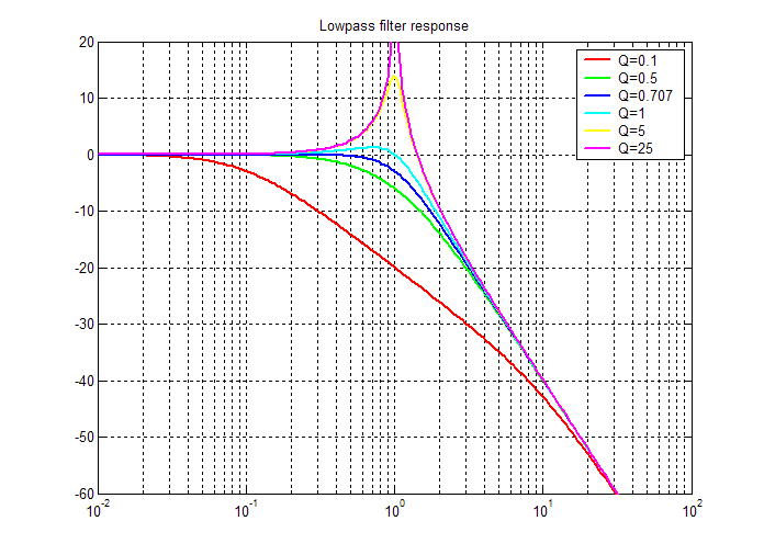
Another down side of this is that the filter performance won't be that great in the pass band and, for instance, if you opted for an active sallen key low pass filter you could get a flatter pass band and initially steeper roll-off because Q-factor won't be limited to values of 0.5 (as they are in a passive RC filter). Here's what I mean: -
A passive 2nd order filter made from two cascaded RC stages would, at best, have a frequency response that follws the green line whereas an active butterworth filter (maximally flat in the pass band) would follow the blue line.


