11
\$\begingroup\$

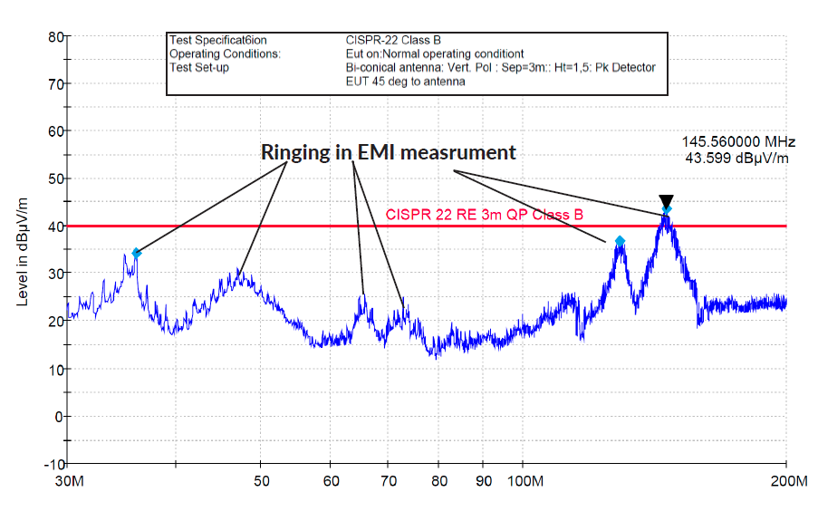
I am working on a device which is undergoing testing to pass FCC part B (CSRR 22) emissions. At one angle and polarization (Vertical) the device fails as it has emissions in the 100-200Mhz range which breach the threshold.

The test result shows two characteristic peaks at 145Mhz and 128Mhz. One source of wider band noise is ringing. The ringing has multiple harmonic components.

Problem

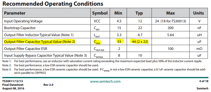
The PCB has 2 Switch Mode power Supplies (SMPS) These are Semtec TS30011/12/13 series chips. (DATASHEET) Upon closer inspection, there is a ringing on the power output (before the inductor stage) SMPS 1 has a ring at 145MHz while SMPS2 has a ring at 128Mhz. It is worth noting that they have different loads on them. Their schematics are identical their layout is some what different but 80% the same.

  1. What layout options do I have to reduce the EMI noise?
  2. I am busy adjusting the trace thickness going into the inductor to reduce stray capacitance

Note there is a GND pour which is not seen in the layout which ties all the Caps together fairly well

I am at a loss for how to adjust the filter components to reduce the ringing.

Test Results (3M, Vertical Pol.)

EMI test results

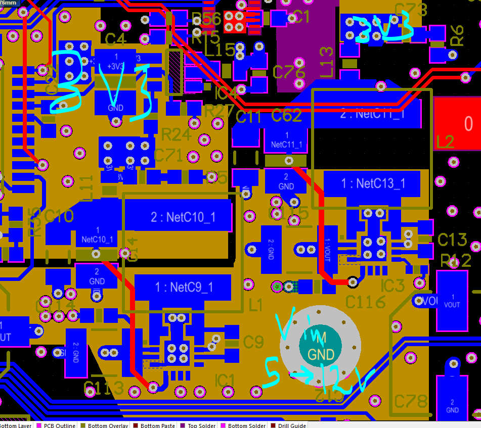
Schematics and Layout of 1

enter image description here This can be solved by placing a ferrite core onto the power supply cable going into the device, however this is a non-optimal solution for various cost and aesthetic reasons.

Pre inductor measurements

enter image description here

Layout of Both SMPS next to each other

The all run reference to GND which is hidden, the power layer below supplies Vin at 5-12V they each are fixed to output 3V3 SMPS next to each other
\$\endgroup\$
12
  • \$\begingroup\$ You speak of a ferrite core on the cable, can you elaborate a bit? What is solved exactly? Also, your layout looks quite similar to the suggested from the manufacturer, but why the additional vias for PGND right where the SW trace is? \$\endgroup\$ Commented Nov 20, 2016 at 0:26
  • \$\begingroup\$ Output capacitors seems huge with around 200 µF, you should try with only one 47uF or two 47uF. What is L11 ? Why do you a have a second series inductor to the final voltage ? I think you have some kind a bottleneck here. Is it a PI filter ? Orange areas are sitting on a layer just under inductors or on the other side ? \$\endgroup\$
    – zeqL
    Commented Nov 20, 2016 at 0:32
  • 4
    \$\begingroup\$ +1 for a well formed question, but why do you want to mess with the output filter? The fact putting a ferrite clamp on the power input improves things says that is the antenna, and something needs to be done on the input side, probably adding an on-board ferrite or a couple decades of capacitance, or a combination of the two. \$\endgroup\$
    – Matt Young
    Commented Nov 20, 2016 at 2:42
  • \$\begingroup\$ Those output capacitors are huge. You could be well up the rising side of the esr curve. Have you tried just tacking a smaller (0.1uF) cap across the output capacitors? Also, add more vias from the caps to ground. The one ground via per-capacitor is going to have a decent amount of inductance. The datasheet has the caps grounded to a pour tied to ground with 8 vias for a reason. \$\endgroup\$ Commented Nov 20, 2016 at 2:49
  • 1
    \$\begingroup\$ The power converter has Vin and switch node pins adjacent. The solid pour under them will definitely couple some switching noise right back into the input (pin pairs 1 and 2, 11 and 12 are where to look). That is at least one issue that I have seen in the past. \$\endgroup\$ Commented Nov 20, 2016 at 17:22

2 Answers 2

3
\$\begingroup\$

Switching nodes are very short which is a good thing. But I don't understand the stubs on the traces to the inductor, you should delete them along with the two additional GND vias. This is not very useful.

Even if there a GND layer, I would not make the orange planes goes under the inductors. Do the same for L1 as for L2, nothing under the inductor. You would avoid any coupling.

I really think output capacitors are too high. Semtech recommand a typical 44µF and you're at 200µF. Try removing the 150µF capacitor.

enter image description here

Also try to increase GND vias of C11, C62 and C10, C42, with at least 2 GND vias each, because if you have 3A current, it will flow through only two GND vias but 6 power vias. Same for C4 decoupling cap, try at least 2 GND vias.

Edit: I really don't understand the use of a ferrite bead and snubber at the end of a SMPS. FB are more used to prevent a power rail to get noise back into the main power rail, for example with PLL power rail. But the voltage after une main inductor should be within noise tolerance, especially for a 3.3V rail.

You may have a ringing due to improper use of FB, look at LC resonant frequency on this Analog Devices' paper : http://www.analog.com/en/analog-dialogue/articles/ferrite-beads-demystified.html

\$\endgroup\$
-2
\$\begingroup\$

The design has the classic ringing on the switching edge. Typical cause of the ringing is in parasitic inductances in the switch transistors, which form parasitic tank circuits together with other parasitics. The ringing is caused by too fast switching edges. There is a nice application note 045 from Richtek that has several tips on how do reduce or eliminate the problem.

As I can also see, the manufacturer's reference schematics (and test boards) includes a "catch" (Schottky) diode, which is missing from the design. The diode parasitics could help to stabilize/damp the ringing on switch side [even if the diode is optional for synchronous converter].

CLARIFICATION: The SEMTECH manufacturer'r reference design uses "optional" PMED4030ER,115 diode in their test/demo board, which has 250 pF of parasitic capacitance at 1 V. The Richtek appnote 045 about RC snubbers came to RC of the order of 330pF/9 Ohms to suppress the ringing. So it is quite likely that the diode might improve both switcher efficiency AND reduce ringing.

\$\endgroup\$
2
  • 4
    \$\begingroup\$ This is a synchronous part. The diode is not necessary. \$\endgroup\$
    – Matt Young
    Commented Nov 20, 2016 at 2:40
  • \$\begingroup\$ While It might be theoretically unnecessary, but practically a parallel Schottky rectifier reduces losses in low-side FET, as explained in this white paper form Fairchild/ON, fairchildsemi.com/technical-articles/… While some other SEMTECH regulators (as SC4620) do explicitly mention the integrated Shcottky diode, specifications for the particular TS3001x IC do not mention this important feature. \$\endgroup\$ Commented Nov 20, 2016 at 8:30

Your Answer

By clicking “Post Your Answer”, you agree to our terms of service and acknowledge you have read our privacy policy.

Not the answer you're looking for? Browse other questions tagged or ask your own question.