2
\$\begingroup\$

I plan to run about 4-5 arduino pro micro in my backyard to handle controlling of solenoid valves for garden watering based on measurements of soil (so we keep it well watered).

My question regards the supply voltage, I wish to use cat 6 over maybe a 20m run in total to supply both power and RS485 networking over the twisted pairs.

Based on previous answers regarding cat6 I know the amperage should be fine assuming all arduino even run full without sleep around 45mA that's some 250mA.

The solenoid valve says 8w at 12v which is 0.6A, assuming the current is required to keep it open (not closed - is this correct?) which I'd hope so otherwise loss of power would cause it to open.

I guess I'd need to run 12v anyway, should I run 12v and 5v down the pairs? If I run just 12v I need a linear voltage regulator, which get quite hot does that mean they are inefficient? If I run 5v as well, how well does 5v perform over that distance due to voltage drop on cat6 pairs?

\$\endgroup\$
2
  • \$\begingroup\$ Do you plan to use the Arduino/AVR UART in 9-bit (multidrop addressing) mode, or are you open to other protocols? Also, do you have a central control station of some type, and if so, what is it? \$\endgroup\$ Commented Nov 23, 2016 at 1:51
  • \$\begingroup\$ Sorry should have mentioned. It will be coordinated by a raspberry pi who will regularly "check in" with the nodes. So the arduino won't speak until spoken to first. I was going to use a MAX485, and output binary structs I'm imagining. I'd give each node an ID, and let the host identify it in the data blob. \$\endgroup\$ Commented Nov 23, 2016 at 1:57

2 Answers 2

3
\$\begingroup\$

In general, higher voltage means lower loss, so you do want to run highest economical voltage (but not more than 48V, this will be dangerous). I also recommending running a single voltage, but using two wires -- for example, orange/or-white for (+) and blue/blue-white for (-). This just makes wiring easier, and significantly decreases the chances of microcontrollers spontaneously rebooting due to interference or ground loops.

First, lets see if you can use 12V. 20 ft of 23 AWG cable will have the resistance 0.4 ohm (assuming 20 ohm/1000 ft, and two wires in parallel for gnd and Vcc). At 0.6A, you will lose 0.24V, which solenoids are not going to notice. If you run 5 solenoid valves at once using a single cable, they will draw 3A total, and a cable will will drop 1.2 volt, still enough to energize the solenoids. So yes, looks like we can run 12V only.

Note that if you needed more power, you would have to go to 24V or 48V, and have 12V regulator in each box.

Now to get 5V, you can use linear or switching regulator. The advantages of linear regulator is that it is simple and already present on some arduinos ( not on pro micro). At 45mA, it will waste 0.3W, which is not a lot and easily dissipated. However, given that switching 5V regulators are less than $2 each on ebay, I highly recommend you just buy a dozen of them and use them everywhere.

\$\endgroup\$
5
  • \$\begingroup\$ Thanks, nearly spot-on! I'm actually using about 20m, not ' so that would be more like 1V drop right? Also here's my actuator - adafruit.com/product/997. I'd water them in turn not all at once, and they don't require voltage when closed so that's even less. Sounds like 12v is the way to go, and it will work. Finally prefer a switching over linear DC converter. \$\endgroup\$ Commented Nov 23, 2016 at 2:29
  • \$\begingroup\$ Also as a follow-up I am using clones with atmega328 that state it can use 12v -> aliexpress.com/item/… \$\endgroup\$ Commented Nov 23, 2016 at 2:38
  • 1
    \$\begingroup\$ re solenoid: "We tried this solenoid at various DC voltages and found we could actuate it down at 6VDC" - this means you can tolerate lots of voltage drop. re built-in regulator on cheap arduinos: I've had the bad experience with them -- the regulator would break with overvoltage as low as 13V. So a freshly charged lead-acid battery produces enough voltage to fry 12V arduino input. \$\endgroup\$
    – theamk
    Commented Nov 23, 2016 at 2:45
  • \$\begingroup\$ I'll be running it from a "12v" PSU but I've seen these go as high as 13v anyway so thanks for the warning. Would those (steel cage like) power supplies that have voltage "trim" be trustworthy once you tune the voltage to 12v precisely? \$\endgroup\$ Commented Nov 23, 2016 at 3:02
  • 1
    \$\begingroup\$ In general, the switching PSUs are usually pretty stable over time. Also, make sure you have freewheeling diodes on all of your coils, otherwise the energy stored in the coils may fry the regulators when they are turned off. \$\endgroup\$
    – theamk
    Commented Nov 23, 2016 at 3:06
1
\$\begingroup\$

Power this baby up!

First off, while running 12V for power would be at least somewhat practical given the constraints in your question, it does limit you as to the amount of current you have available. Using 24 or 48V with buck regulators down to 12V at each endpoint (these are available as modules from a variety of sources) will likely be a less lossy and perhaps somewhat more reliable approach overall.

Talk to me....

Second, there is a problem on the data side as well -- the Pi's UART doesn't really support the multidrop addressing system (9-bit UART mode) that is commonly used with RS-485 networks and microcontroller UARTs. I'd recommend going with either an external UART for the Pi that can support the 9-bit mode properly, or using an I2C-over-RS485 network instead of UART-over-RS485.

External UARTs for the Pi

Thankfully, SPI UART ICs are available relatively cheaply and support the 9-bit mode as well as other functions useful for RS-485 (such as automatic control of the RS-485 transceiver direction control pins). Some USB->UART chips can also support this function; read the datasheet for what you're using for the details.

Using I2C over RS-485

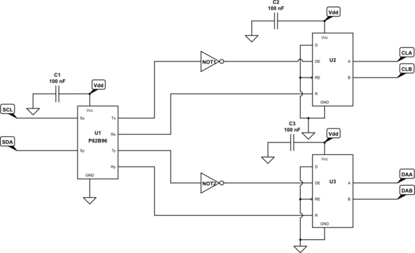
The I2C bus provides several very nice features -- multidrop addressing, contention detection, and multi-mastering support, all right out of the box. "But, how are you going to get it to go 20m over twisted pair?" you ask. Simple: we take RS-485 and use it as the physical layer for our I2C link with the aid of the P82B96 buffer IC. This chip splits the bidirectional I2C signals into two unidirectional signals each for SCL and SDA -- from there, it's possible to use modern RS-485 transceivers that implement an open-bus/floating-bus fail-safe in a pseudo-open-drain way (i.e. wire DE to the complement of TX and D to 0), as depicted in the schematic below -- U2 and U3 are the RS-485 transceivers, and the NOT gate can be whatever you have on hand that runs off of the supply voltage available.

schematic

simulate this circuit – Schematic created using CircuitLab

(You'll need 3.3V transceivers for U2 and U3 to use this with the Pi BTW.)

\$\endgroup\$
12
  • \$\begingroup\$ very interesting! I'm attempting to come to terms with the I2C over RS-485 (more of a bonus response, thanks!) It looks like we've got three P82B96 in this example, one acting as a modulator and two acting as demodulators, effectively modems for I2C over RS-485? In this case then, we've taken the clock and data signals and split it into a pair(one per direction). Is that about the gist of it? My original plan was to just use a USB-> RS485 on the raspberry pi and a max-485 for the arduinos. \$\endgroup\$ Commented Nov 23, 2016 at 3:47
  • \$\begingroup\$ @MitchellCurrie -- U1's the only P82B96 in the schematic, U2 and U3 are RS-485 transceivers. But yes, the overall circuit effectively is a modem of sorts for I2C over RS485, and splits the clock and data into a bidirectional differential pair for each. \$\endgroup\$ Commented Nov 23, 2016 at 3:51
  • \$\begingroup\$ I see. Right so it takes a pair of them to make the 4-wire output for our I2C over RS485. I suppose I have the available wire-pairs in 8-core CAT6. I'll need to give this some thought, it would seem simpler just to wire up with a usb adaptor. In my mind, the prime benefit of I2C is the fact it has addressing modes built into the protocol - is that right? \$\endgroup\$ Commented Nov 23, 2016 at 4:04
  • \$\begingroup\$ second follow-up: with let's say 48V PSU, what's the efficiency like of let's say an arduino that needs 0.25W (50mA @ 5v) from 0.25W (5mA @ 48V). If a switching PSU, they are normally around 90% efficient if my recollection is correct. \$\endgroup\$ Commented Nov 23, 2016 at 4:07
  • \$\begingroup\$ A good buck converter module should be 80-90% efficient at getting 48V down to 5V -- they're fairly common from telecoms work \$\endgroup\$ Commented Nov 23, 2016 at 4:21

Your Answer

By clicking “Post Your Answer”, you agree to our terms of service and acknowledge you have read our privacy policy.

Not the answer you're looking for? Browse other questions tagged or ask your own question.